ILS
by Ghost Aviator
✈ Chapter 9: ILS
Instrument Landing System
📋 Contents
1. Introduction 2. ILS Components 3. ILS Frequencies & Pairing 4. Identification & Monitoring 5. Marker Beacons 6. ILS Coverage 7. Principle of Operation 8. Displays & Interpretation (CDI, HSI) 9. ILS Categories (ICAO) 10. Errors, Accuracy & Protected Areas 11. ILS Calculations 12. ILS Summary 13. Practice Questions (14 Q)1. Introduction
The Instrument Landing System (ILS) is the most accurate approach and landing aid in current use. It has been in existence for over 40 years and is the ICAO standard precision approach system.
- Precision approach system — provides guidance in both horizontal and vertical planes
- Enables automatic landings (autoland) in Cat III conditions
- Guides the pilot from the coverage limit down to Decision Height (DH)
- At DH: land (if required visual references exist) or execute missed approach
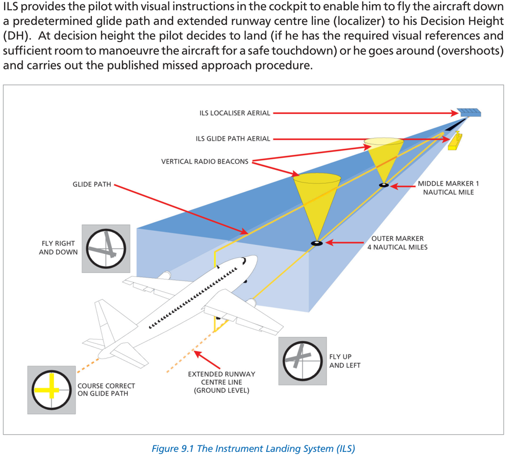
2. ILS Components
| Component | Function | Location | Band |
|---|---|---|---|
| Localizer (LLZ) | Lateral (left/right) guidance — runway centreline | ~300 m from upwind end of runway | VHF |
| Glide Path (GP) | Vertical (up/down) guidance — glide slope | 300 m from threshold, ~200 m from runway edge abeam touchdown | UHF |
| Marker Beacons | Range check — cross-check height vs distance | OM, MM, IM at set distances from threshold | VHF 75 MHz |
- Locator (L): Low-powered NDB co-located at the OM beacon site
- DME: Frequency-paired with ILS; zero-referenced to runway threshold; supplements or replaces marker range information
- Back Course: Non-precision approach on back beam of localizer (approved in some countries; NOT permitted in UK)
3. ILS Frequencies & Pairing
- Selecting the localizer frequency automatically activates the GP receiver
- Reduces pilot workload — one selection activates both
- Reduces potential for wrong frequency selection
- Only one identifier needed for both localizer and glide path
DME Paired with ILS
- DME ranges are zero-referenced to the ILS runway threshold
- Protected within ILS localizer service area up to 25,000 ft
- May also be used for published SIDs and STARs (with extended coverage when notified)
- Do not use DME outside stated limits — may give errors
4. Identification & Monitoring
- 2 or 3-letter Morse code; first letter is usually “I”
- Transmitted at 7 groups per minute
- Only one ident needed (shared by localizer and GP)
- Ident automatically suppressed if ILS becomes unserviceable
- During maintenance: ident replaced by continuous tone or removed completely
- If ident is a continuous tone → ILS under maintenance → DO NOT USE
- If ident ceases during approach → ILS is unserviceable → discontinue immediately
- Unserviceable glide path only: ATC will warn; do not use GP
Ground Monitoring
| Parameter | Cat I Limit | Cat II Limit | Cat III Limit |
|---|---|---|---|
| Localizer shift from centreline | > 35 ft | > 25 ft | > 20 ft |
| Glide path angle change | > 0.075 × basic GP angle | ||
| Power reduction | > 50% | ||
5. Marker Beacons
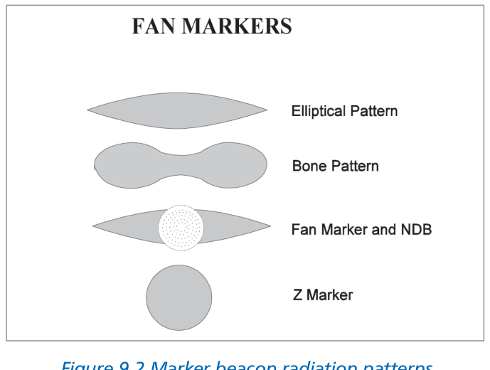
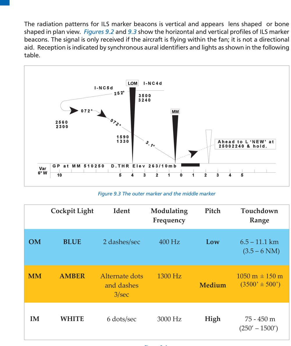
Markers transmit at 75 MHz in a narrow fan-shaped vertical beam. The signal is received only when the aircraft flies through the fan (not directional). Reception is indicated by synchronous aural tones and cockpit lights.
| Marker | Cockpit Light | Ident Signal | Audio Freq | Range from Threshold |
|---|---|---|---|---|
| OM (Outer) | BLUE | 2 dashes/sec | 400 Hz (Low pitch) | 6.5 – 11.1 km (3.5 – 6 NM) |
| MM (Middle) | AMBER | Alt dots & dashes 3/sec | 1300 Hz (Medium pitch) | 1050 m ± 150 m (3500′ ± 500′) |
| IM (Inner) | WHITE | 6 dots/sec | 3000 Hz (High pitch) | 75 – 450 m (250′ – 1500′) |
6. ILS Coverage
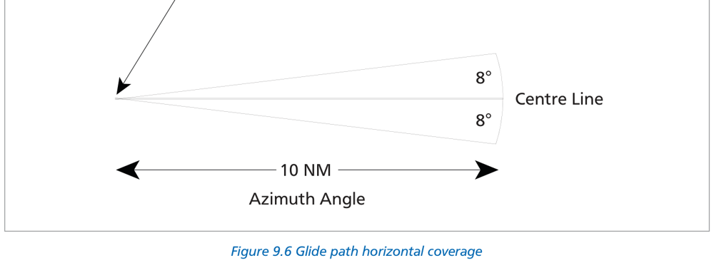
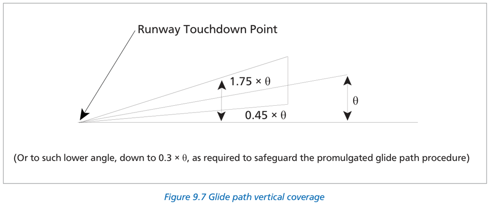
| Sector | Range |
|---|---|
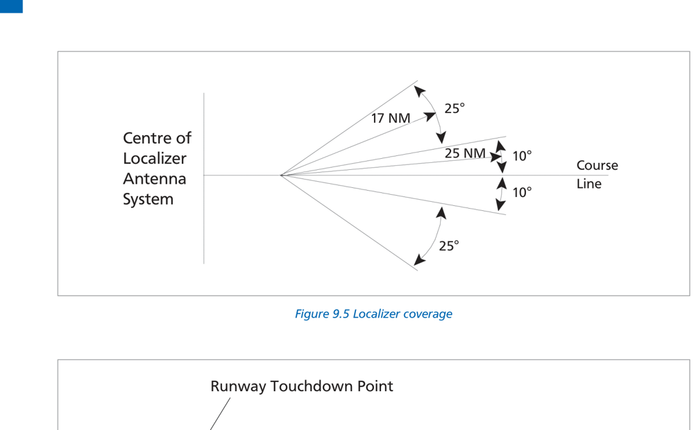
| Within ±10° of centreline | 25 NM (46.3 km) |
| 10° to 35° from centreline | 17 NM (31.5 km) |
| Outside ±35° | 10 NM (18.5 km) if provided |
| Parameter | Value |
|---|---|
| Azimuth coverage | ±8° either side of centreline |
| Range | At least 10 NM |
| Vertical — upper limit | 1.75 × θ above horizontal |
| Vertical — lower limit | 0.45 × θ (may reduce to 0.3θ if required) |
7. Principle of Operation
7.1 Localizer
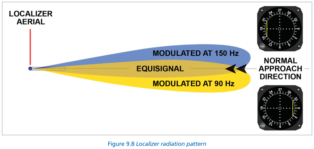
| Sector | Frequency | Colour Code | CDI Indication |
|---|---|---|---|
| Left-hand lobe (aircraft left of ℅) | 90 Hz | Yellow | Needle deflects RIGHT → Fly Right |
| Right-hand lobe (aircraft right of ℅) | 150 Hz | Blue | Needle deflects LEFT → Fly Left |
| On centreline | DDM = 0 | — | Needle centred |
DDM (Difference in Depth of Modulation) increases with distance from the centreline. The DDM drives the vertical needle of the CDI/HSI.
“90 = Yellow = Left = Fly Right”
7.2 Back Course ILS
- Glide path indications are incorrect (would guide to wrong end of runway)
- CDI needle sense is REVERSED for back course approach (HSI gives correct sense if front QDM selected)
- No range-check markers available
- Not permitted in the UK — ignore any back course indications in UK
7.3 Glide Path
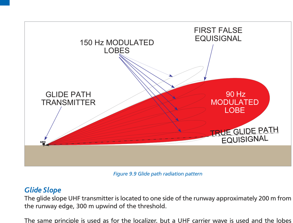
| Lobe | Modulation | Aircraft Position | CDI Indication |
|---|---|---|---|
| Upper lobe (large) | 90 Hz | Aircraft above GP | GP needle deflects DOWN → Fly Down |
| Lower lobe (small) | 150 Hz | Aircraft below GP | GP needle deflects UP → Fly Up |
| On glide path | DDM = 0 | On the GP | GP needle centred |
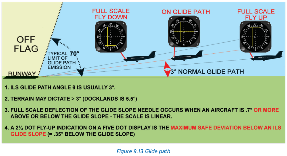
Standard GP angle: 3° (ICAO requirement: 2° – 4°).
GP transmitter: UHF, located ~300 m upwind of threshold, ~200 m from runway edge.
7.4 False Glide Slopes
- Caused by metallic structure reflections and antenna height/propagation characteristics
- First false GP at approximately twice the promulgated glide path angle
- For standard 3° GP: first false GP at approximately 6°
- False GPs always occur above the true glide slope
- Normal practice: intercept glide slope from below
- At Heathrow: continuous descent approach may capture GP from above — confirm height with DME/markers
8. Displays & Interpretation
8.1 CDI (Course Deviation Indicator) in ILS Mode
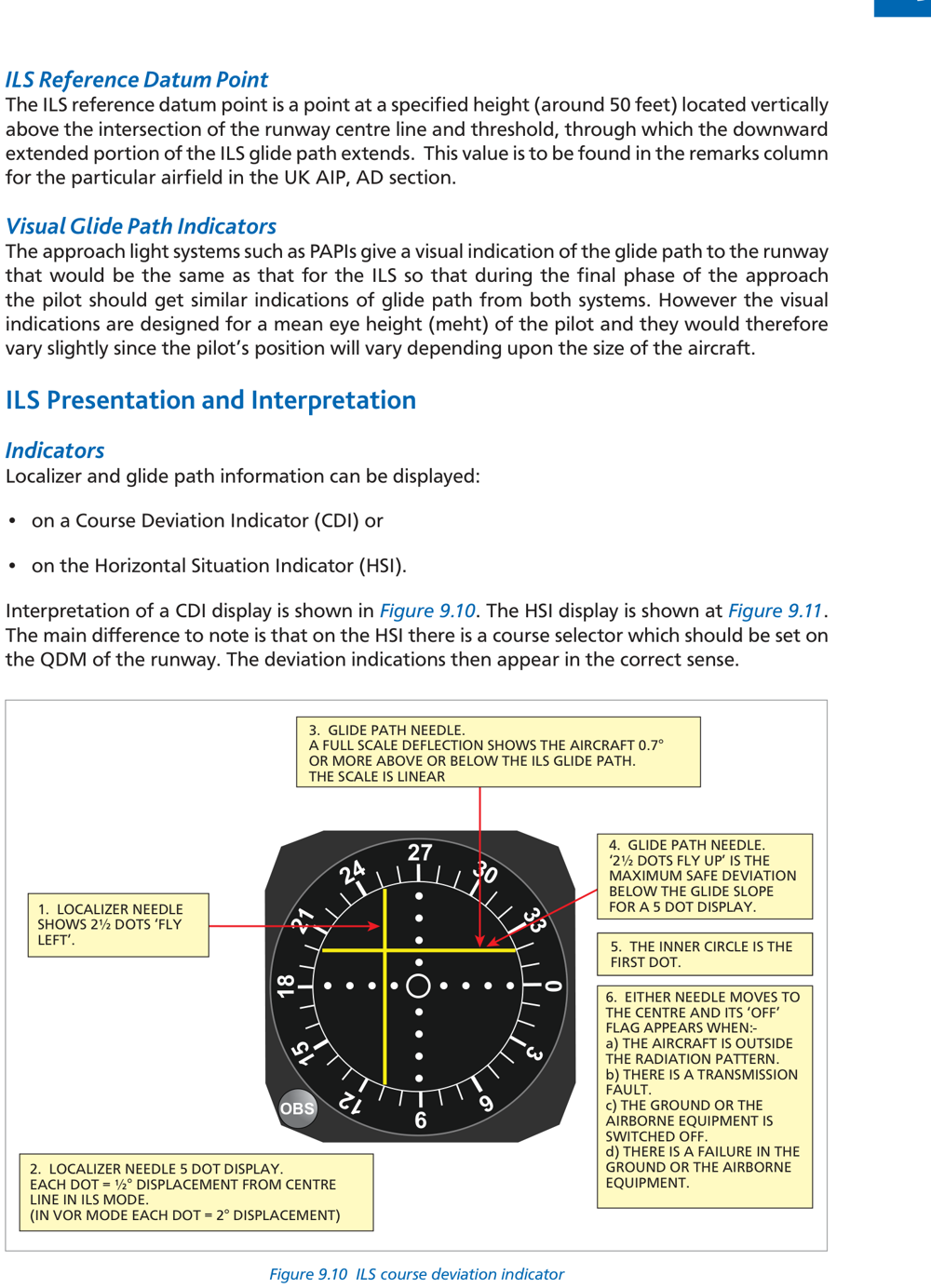
| Parameter | Localizer | Glide Path |
|---|---|---|
| Sensitivity | 0.5° per dot | 0.14° per dot |
| Full Scale Deflection | ±2.5° (= 5 dots) | ±0.7° (= 5 dots) |
| Max safe deviation below GP | — | 2.5 dots fly up (= 0.35°) |
Compare with VOR mode: CDI sensitivity = 2°/dot in VOR mode, 0.5°/dot in ILS mode. 5× more sensitive!
- If left/right localizer deviation exceeds half full scale (>2.5 dots) → initiate immediate go-around
- If glide path fly-up exceeds 2.5 dots fly up → initiate immediate go-around (terrain clearance may be compromised)
8.2 HSI (Horizontal Situation Indicator) in ILS Mode
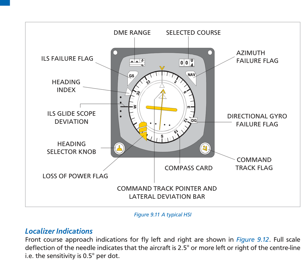
- Course selector should be set to the QDM of the runway
- Deviation bar and GP needle give correct sense indications
- HSI gives correct sense even on back course (if front course QDM is set)
- Azimuth failure flag, ILS failure flag, and loss of power flag visible
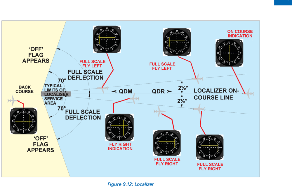
8.3 Localizer On-Course Indications
| What you see | What it means | Action |
|---|---|---|
| Localizer bar right | Aircraft LEFT of centreline | Turn RIGHT |
| Localizer bar left | Aircraft RIGHT of centreline | Turn LEFT |
| GP needle high (fly up) | Aircraft BELOW glide slope | Pitch UP / reduce descent |
| GP needle low (fly down) | Aircraft ABOVE glide slope | Pitch DOWN / increase descent |
9. ILS Categories (ICAO)
| Facility Cat | Glide Path Height at Reference Datum |
|---|---|
| Category I | Guidance to ≤ 200 ft (60 m) above threshold horizontal plane |
| Category II | Guidance to ≤ 50 ft (15 m) above threshold horizontal plane |
| Category III | Guidance from coverage limit to and along the runway surface |
| Operational Cat | Decision Height (DH) | RVR |
|---|---|---|
| Cat I | ≥ 200 ft (60 m) | ≥ 550 m |
| Cat II | ≥ 100 ft (30 m), < 200 ft | ≥ 300 m |
| Cat IIIA | < 100 ft (30 m) or no DH | ≥ 200 m |
| Cat IIIB | < 50 ft (15 m) or no DH | ≥ 75 m but < 200 m |
| Cat IIIC | No DH | No RVR limitation |
10. Errors, Accuracy & Protected Areas
- Beam bends: Caused by atmospheric conditions — smooth, slow deflections
- Scalloping: Caused by reflections → rapid needle fluctuations impossible to follow
- Beam noise: Generated by transmitter interference
| Area | Definition | When Enforced |
|---|---|---|
| Critical Area | Defined area around LLZ and GP antennae where vehicles/aircraft excluded | ALL ILS operations (any category) |
| Sensitive Area | Extends beyond critical area; controls parking/movement of vehicles/aircraft | Low visibility operations only |
| Cat II/III Hold | Pre-take-off holding points further from runway than in good weather | Cat II and III ops; marked with signs and red stop bars |
- Weather: Snow and heavy rain attenuates ILS signals, reducing range and accuracy
- FM Broadcasts: FM stations below 108 MHz can overspill into radio nav band. FM suppression circuits mandatory in ILS receivers since late 1990s.
- Serviceability check: Ensure failure flags not visible; monitor ident throughout approach
11. ILS Calculations
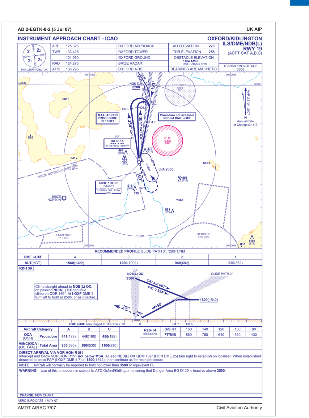
| Segment | Between | Notes |
|---|---|---|
| Initial approach | From entry to IAF (Initial Approach Fix) | Sector Safety Altitudes (SSA) apply |
| Intermediate | IAF to FAF (Final Approach Fix) | Intercept localizer and configure aircraft |
| Final approach | After FAF to DH/touchdown | ILS guidance; check markers/DME |
Height Check on Glide Path (1:60 Rule)
Height (ft) = GP angle × Range (NM) × 100
(Simplified from the 1:60 rule: GP angle × range/60 × 6076 ft ≈ GP angle × range × 100)ROD (fpm) = 5 × Groundspeed (kt)
For other GP angles: calculate for 3° then ÷3 × actual angle.Expected height = 3 × 4 × 100 = 1200 ft (exact trig = 1274 ft)
ROD required = 5 × 150 = 750 fpm (exact trig = 796 fpm)
12. ILS Summary
| Component | Details |
|---|---|
| Localizer | VHF 108–111.975 MHz, 40 channels (odd tenths), antenna at upwind end |
| Glide Path | UHF 329.15–335 MHz, frequency paired, antenna abeam touchdown |
| Markers | 75 MHz, fan-shaped vertical radiation, OM/MM/IM |
| DME | Frequency paired, zero-referenced to threshold, replaces/supplements markers |
| Ident | 2–3 Morse letters, 7 groups/min, first letter “I”; suppressed when u/s; continuous tone = maintenance |
| OM | Blue, 2 dashes/sec, 400 Hz, 6.5–11.1 km from threshold |
| MM | Amber, alt. dots & dashes 3/sec, 1300 Hz, 1050 m from threshold |
| IM | White, 6 dots/sec, 3000 Hz, 75–450 m from threshold |
| Monitor triggers | LLZ: >35/25/20 ft shift; GP: >0.075θ change; power >50% reduction |
| LLZ coverage | 25 NM/±10°, 17 NM/±35° |
| GP coverage | 10 NM/±8°, 0.45θ to 1.75θ vertical |
| LLZ principle | LH lobe 90 Hz (yellow), RH lobe 150 Hz (blue); DDM=0 on ℅ |
| GP principle | Upper lobe 90 Hz, lower lobe 150 Hz; DDM=0 on GP |
| False GP | First false at ~2× GP angle (6° for standard 3° GP) |
| CDI localizer | 0.5°/dot, FSD ±2.5° |
| CDI glide path | 0.14°/dot, FSD ±0.7°; max safe dev = 2.5 dots fly up |
| Height formula | GP angle × range (NM) × 100 = height (ft) |
| ROD formula (3°) | 5 × groundspeed (kt) = ROD (fpm) |
13. Practice Questions
Localizer: 35° from centreline out to 17 NM; ±10° out to 25 NM. The coverage narrows to 17 NM within the wider ±35° sector.
Upper = 1.75 × 3.5° = 6.125°; Lower = 0.45 × 3.5° = 1.575°.
First false GP ≈ twice the true GP angle = 2 × 3° = 6°. False GPs always occur above the true glide slope.
MM = Amber light + alternating dots and dashes at 3 per second + 1300 Hz medium pitch audio.
Stronger 150 Hz on localizer = aircraft in RIGHT (blue) lobe = aircraft is RIGHT of centreline → fly LEFT.
Stronger 150 Hz on GP = aircraft BELOW glide slope (lower lobe = 150 Hz) → fly UP.
Combined: UP and LEFT.
Upper = 1.75 × 3° = 5.25°; Lower = 0.45 × 3° = 1.35°.
Cat II ILS ground installation provides guidance to the point where the glide path intersects at 50 ft (15 m) above the threshold horizontal plane.
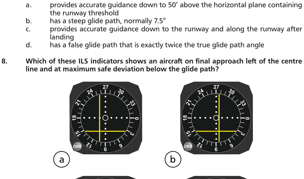
Aircraft LEFT of centreline → localizer bar deflects RIGHT. Below glide path at maximum safe deviation (2.5 dots fly up) → GP needle shows fly up, 2.5 dots. This is option (d).
Outside the coverage sectors, the ILS may give false on-course or reverse sense signals. The signal exists outside the protected coverage area but cannot be guaranteed to give correct guidance.
OM = Blue light + 2 dashes per second (400 Hz, low pitch).
Maximum safe deviation below glide slope = 2.5 dots fly up (half the 5-dot full scale). Beyond this, initiate immediate go-around as terrain clearance may be compromised.
Outside coverage: localizer may give false on-course and reverse sense indications; glide slope may give intermittent and incorrect indications. Answer (d) correctly states this combination.
GP horizontal coverage: ±8° azimuth out to at least 10 NM.
Runway QDM 264° (westward). Standing at the runway facing approach (264°), LEFT is to the south, RIGHT is north.
90 Hz on localizer = aircraft in LEFT (yellow) sector = aircraft is south of centreline (left of runway facing west, looking east).
90 Hz on GP = upper lobe = aircraft is above glide slope.
Answer: south, above glide slope.
Chapter 9 — ILS (Instrument Landing System)
Ghost Aviator | www.ghostaviator.com
For personal study use only.
Reinforce Chapter 9: ILS
Test your knowledge and practice actual exam questions for Radio Navigation.