10
RADIO NAV — CHAPTER 10 · NOTES
MLS
by Ghost Aviator
Ghost Aviator
www.ghostaviator.com
Ghost Aviator
www.ghostaviator.com
Ghost Aviator
DGCA CPL / ATPL Study Notes • Radio Navigation • Ch 10
✈ Chapter 10: MLS
Microwave Landing System
📋 Contents
1. Introduction & ILS Disadvantages 2. The MLS System 3. Principle of Operation (TRSB) 4. Airborne Equipment 5. MLS Summary 6. Practice Question1. Introduction & ILS Disadvantages
The Microwave Landing System (MLS) was designed to replace ILS as the ICAO standard precision approach system, overcoming ILS limitations while providing greater flexibility. However, few MLS installations exist and they co-exist with ILS.
⚠ Why ILS Needed Replacing — ILS Disadvantages
- Only 40 channels available worldwide
- Fixed and narrow azimuth/glide slope beams → aircraft must be sequenced → landing delays
- No special procedures for helicopters, slower aircraft, STOL aircraft
- Cannot be sited in hilly terrain; requires large flat cleared land
- Vehicles, taxiing aircraft and buildings must be kept well clear to prevent beam bending
2. The MLS System
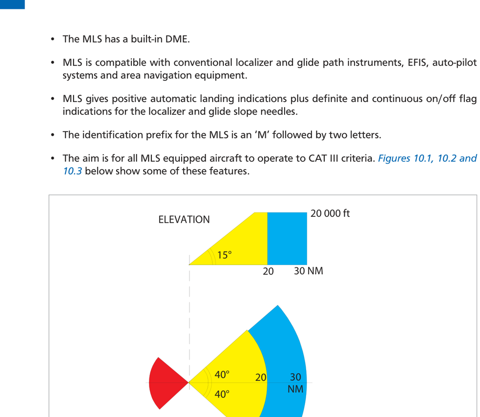
Fig 10.1: MLS coverage — ±40° azimuth, 20–30 NM range, up to 20,000 ft
📡 MLS Key Features
| Parameter | MLS Value | vs ILS |
|---|---|---|
| Channels | 200 | ILS: 40 |
| Frequency band | SHF: 5031–5090.7 MHz | ILS: VHF/UHF |
| Azimuth coverage | ±40° | ILS: ±35° (limited) |
| Glide slope range | 0.9° to 20° selectable | ILS: fixed ~3° |
| Usable range (UK) | 20 NM (up to 30 NM) | ILS: 25 NM/±10° |
| Max coverage height | 20,000 ft | ILS: variable |
| Back course | Secondary system ±20°, 15° elevation, 10 NM, 10,000 ft | ILS: problematic |
| DME | Built-in DME | ILS: optional |
| Ident prefix | M + two letters | ILS: I + letters |
| Aim | CAT III operations | ILS: CAT I/II/III |
✓ MLS Advantages Over ILS
- SHF frequency: sitable in hilly terrain; scanning beam avoids reflections from vehicles/buildings
- 200 channels vs 40 for ILS → less frequency congestion
- Selectable approach paths (curved/segmented) → noise abatement procedures possible
- Pilots choose own approach path within coverage → better runway utilisation
- Compatible with EFIS, autopilot, RNAV and ILS-type displays
- Continuous on/off flag indications
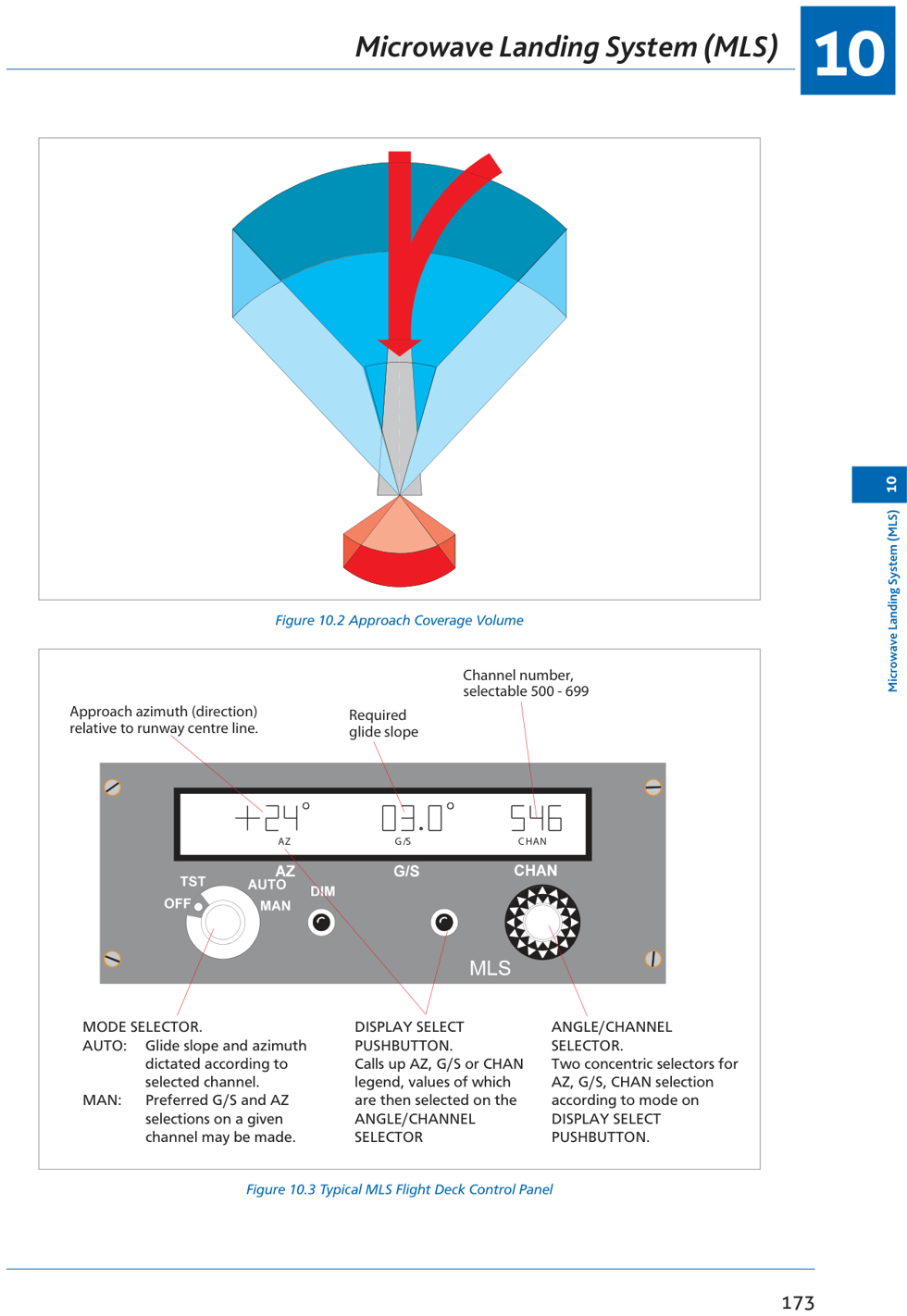
Fig 10.2: MLS approach coverage volume and Fig 10.3: Flight deck control panel
3. Principle of Operation
MLS uses Time Division Multiplexing (TDM) — only one frequency per channel; all ground equipment transmissions are synchronized to avoid interference.
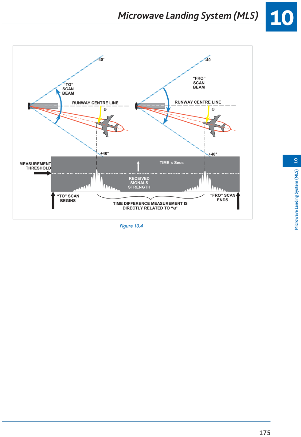
Fig 10.4: TO and FRO scanning beam — time difference proportional to aircraft angular position
📡 Time Referenced Scanning Beam (TRSB)
| Measurement | How It Works |
|---|---|
| Azimuth | Beam sweeps “TO” then “FRO” across the scan sector. Aircraft measures the time interval between the two receptions. Time interval = angular position relative to runway centreline (QDM). |
| Elevation | Second beam sweeps up then down. Aircraft measures time difference between up/down pulses = angular position above horizontal = selected glide slope. |
| Range | Built-in DME (DME/P for Cat II/III — accurate to within 100 ft). |
📡 Other MLS Components
- Back Azimuth: Go-around/departure guidance ±20° up to 15° elevation, 10 NM, 10,000 ft
- Flare: Standard provides for flare elevation (not intended for future implementation)
- Auxiliary data: Station ident, system condition, runway condition, weather information
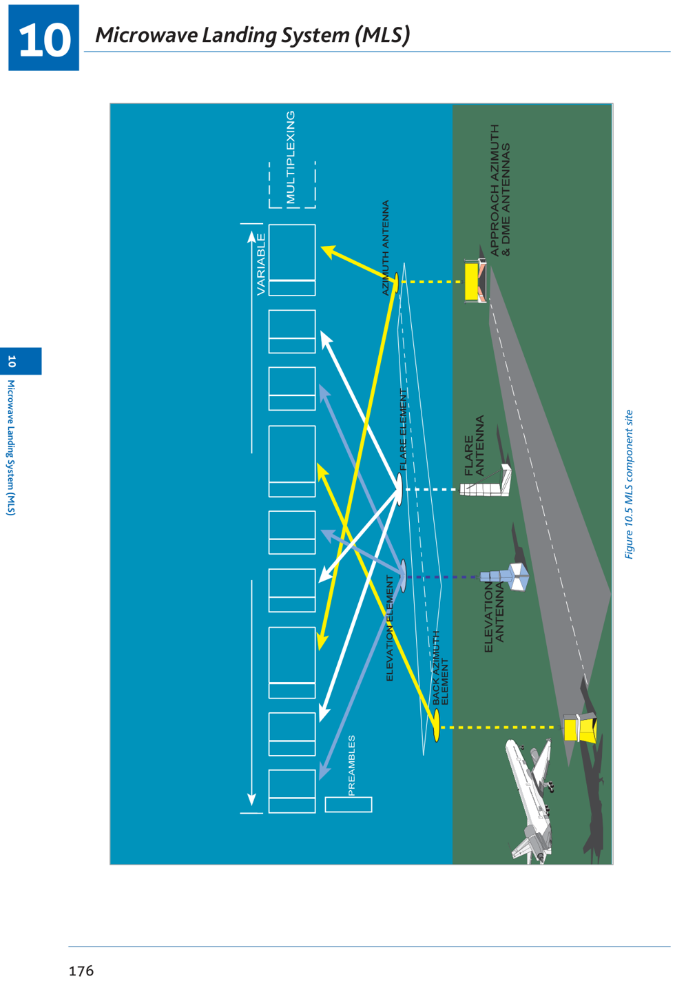
Fig 10.5: MLS component site layout
4. Airborne Equipment
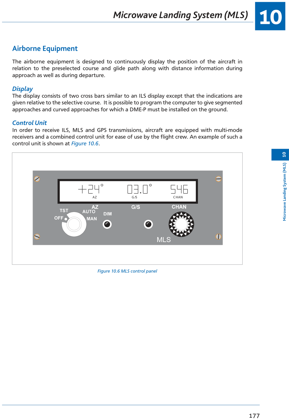
Fig 10.6: MLS control panel — mode selector, display select, angle/channel selector
📡 MLS Airborne Equipment Features
- Continuously displays aircraft position relative to selected course and glide path + distance
- Two cross-bars similar to ILS CDI — indications relative to selected course (not fixed runway QDM)
- Can programme segmented and curved approaches (DME/P required on ground)
- Multi-mode receivers: handle ILS, MLS and GPS from single combined control unit
- Control unit allows selection of: AZ (azimuth angle), G/S (glide slope angle), CHAN (channel 500–699)
- Mode selector: AUTO (G/S and AZ auto per channel) or MAN (preferred G/S and AZ selection)
5. MLS Summary
| Parameter | Details |
|---|---|
| Purpose | Precision approach system; designed to replace ILS |
| Frequency band | SHF: 5031–5090.7 MHz |
| Channels | 200 |
| Principle | TRSB (Time Referenced Scanning Beam) — time between TO/FRO sweeps |
| Azimuth coverage | ±40° of runway QDM |
| Glide slope | 0.9° to 20° selectable |
| Range (UK) | 20 NM; up to 30 NM |
| Range measurement | Built-in DME (DME/P for Cat II/III: ±100 ft) |
| Ident | M + 2 letters |
| Display | Cross-bars (same as ILS CDI); relative to selected course |
| Target category | CAT III |
6. Practice Question
Q1. The coverage of the Microwave Landing System in the UK extends to ___ up to a height of ___ and ___ either side of the on-course line.
(a) 20 NM, 20,000 ft, 40 degrees
(b) 35 NM, 5,000 ft, 40 degrees
(c) 35 NM, 5,000 ft, 20 degrees
(d) 17 NM, 2,000 ft, 35 degrees
Answer: (a)
MLS in the UK: range 20 NM, height 20,000 ft, azimuth ±40° of runway centreline.
MLS in the UK: range 20 NM, height 20,000 ft, azimuth ±40° of runway centreline.
DGCA CPL/ATPL Radio Navigation Study Notes
Chapter 10 — MLS (Microwave Landing System)
Ghost Aviator | www.ghostaviator.com
For personal study use only.
Chapter 10 — MLS (Microwave Landing System)
Ghost Aviator | www.ghostaviator.com
For personal study use only.
Study Radio Nav with other student pilots
Join the free Radio Nav group on Telegram. Stuck on a doubt? Type /q and your question, and get an answer from Ghost Aviator's notes.
LIVE BATCH
Study Radio Navigation live with the Captain
Small batch of 10 · live doubt-clearing · 4–6 weeks · ₹12,999 ₹7,999
Reinforce Chapter 10: MLS
Test your knowledge and practice actual exam questions for Radio Navigation.
Planning your Pilot Training in 2026?
Calculate exact flying hours, DGCA exam fees, and living costs with our interactive calculator.