VOR
by Ghost Aviator
✈ Chapter 8: VOR
VHF Omnidirectional Range
📋 Contents
1. Introduction & Background 2. Principle of Operation 3. Terminology — Radials & Bearings 4. Frequencies & Channels 5. Identification & Monitoring 6. Types of VOR 7. Range & Coverage 8. DOC (Designated Operational Coverage) 9. Accuracy & Errors 10. Cone of Confusion 11. Cockpit Displays — CDI, RMI, HSI 12. In-Flight Procedures 13. VOR Summary Table 14. Practice Questions (33 Q)1. Introduction & Background
VOR — VHF Omnidirectional Range — is the primary short-range radio navigation aid used worldwide. It provides magnetic bearing information to/from a ground station and forms the backbone of conventional airway navigation.
- Adopted by ICAO in 1960 as the standard short-range navaid
- Operates in the VHF band — immune to static interference and skywave
- Provides magnetic bearing to/from the station (azimuth service)
- Emission designator: A9W
- Co-located with DME → VOR/DME; with TACAN → VORTAC
2. Principle of Operation
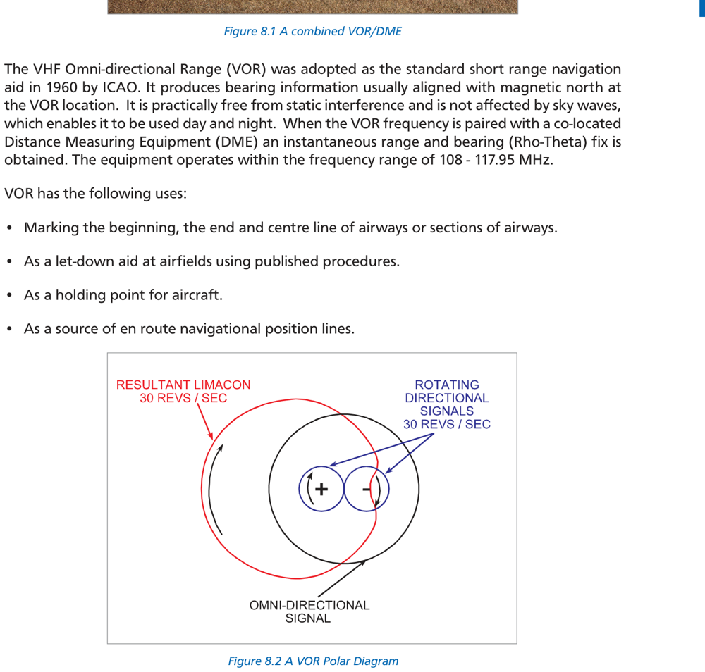
The VOR works by phase comparison of two 30 Hz signals. The phase difference between the two signals equals the aircraft's magnetic bearing from the station (radial).
| Signal | Name | Modulation | Characteristic |
|---|---|---|---|
| Reference | Omnidirectional reference | FM subcarrier (9960 Hz) | Same phase in ALL directions |
| Variable | Directional / variphase | AM on carrier | Phase varies with azimuth (limàcon pattern) |
The variable signal is created by rotating a limàcon (figure-of-eight) radiation pattern at 30 rev/sec. At magnetic north, both signals are in phase. Moving clockwise, the variable signal phase progressively leads the reference — the phase difference equals the radial.
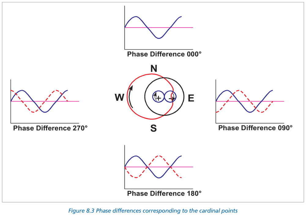
Example: Aircraft due East → phase difference = 90°
CVOR vs DVOR Signal Generation
| Feature | CVOR (Conventional) | DVOR (Doppler) |
|---|---|---|
| Reference signal | FM subcarrier (9960 Hz ±480 Hz) | AM on carrier |
| Variable signal | AM on carrier (rotating limàcon CW) | FM via Doppler (simulated ACW rotation) |
| Site error | More susceptible | Less site error — preferred at complex sites |
| Antenna array | Single rotating antenna | Ring of 48 antennas, switched electronically |
3. Terminology — Radials & Bearings
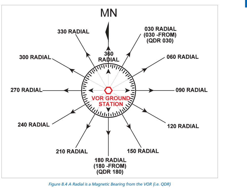
| Term | Definition | Note |
|---|---|---|
| Radial | Magnetic bearing FROM the VOR (QDR) | What the VOR transmits |
| QDR | Magnetic bearing FROM station to aircraft | RMI tail |
| QDM | Magnetic heading to fly TO station (no wind) | RMI head |
| QTE | True bearing FROM station | Apply variation at VOR |
This is opposite to ADF/NDB where variation is applied at the aircraft.
QDR = 090°M → QTE = 090° − 10° = 080°T (subtract westerly variation)
4. Frequencies & Channels
| Band | Range | Channels | Notes |
|---|---|---|---|
| Lower VOR band | 108.000 – 111.975 MHz | 40 channels | Shared with ILS Localiser — even tenths = VOR (108.0, 108.2…); odd tenths = ILS |
| Upper VOR band | 112.000 – 117.975 MHz | 120 channels | VOR exclusive |
This allows 40 VOR + 40 ILS channels in the shared band.
5. Identification & Monitoring
Station Identification
- 3-letter Morse code transmitted every 10 seconds on a 1020 Hz subcarrier
- Some stations also broadcast voice ATIS on the VOR frequency
- Keyed at 7 words per minute
Special Beacon Types
| Type | Ident Signal | Purpose | Use? |
|---|---|---|---|
| TST | TST in Morse | Test beacon — under maintenance/calibration | ❌ DO NOT USE |
| VOT | Continuous dots | VOR Test facility — checks aircraft VOR equipment | ✓ Ground test only |
Maximum permissible error = ±4°
Monitoring
- Built-in monitor checks VOR bearing accuracy continuously
- If bearing error exceeds ±1° → station shuts down or switches to standby transmitter
- During standby switchover: ident is suppressed for 30 seconds
- Rule: NEVER USE a VOR when no ident is heard
6. Types of VOR
| Type | Full Name | Power | Use |
|---|---|---|---|
| CVOR | Conventional VOR | Standard | En-route navigation |
| DVOR | Doppler VOR | Standard | Sites with terrain/structure interference |
| TVOR | Terminal VOR | Low (≤50W) | Airfields — short range approach/departure |
| VOT | VOR Test facility | Very low | Ground equipment check only |
| VORTAC | VOR + TACAN | Standard | Civil (VOR) + Military (TACAN bearing + DME) |
| VOR/DME | VOR + DME | Standard | Provides bearing + distance |
- AM carrier = reference signal
- Ring of 48 antennas switched electronically to simulate a rotating antenna
- Doppler effect creates the FM variable signal
- Simulated rotation is anticlockwise (opposite to CVOR) — receiver processes identically
- Less susceptible to multipath site errors than CVOR
7. Range & Coverage
VOR is a line-of-sight (LOS) system. Range depends on aircraft altitude and terrain.
Range (NM) = 1.25 × (√Htx + √Hrx)
Where H = height in feet above terrain.Note: Coefficient 1.25 is used for all DGCA exam calculations (some texts show 1.23, but exam answers verify with 1.25).
Range = 1.25 × (√10000 + √100) = 1.25 × (100 + 10) = 1.25 × 110 = 137.5 NM
8. DOC — Designated Operational Coverage
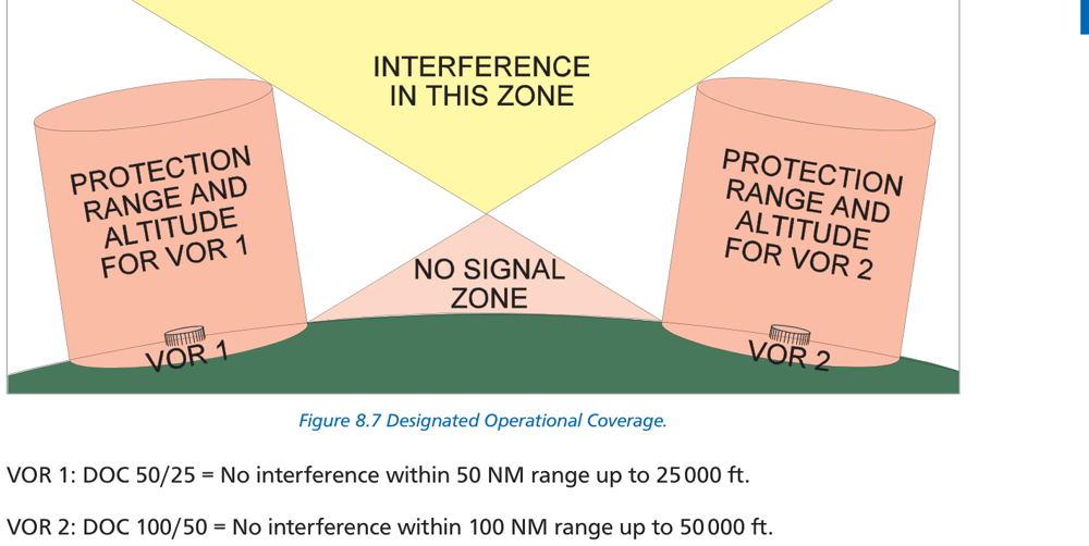
- Specifies the range and altitude within which the VOR provides reliable navigation service
- Published as a range/altitude pair — e.g., 50 NM / FL 250
- Means: reliable up to 50 NM from the station at or below FL 250
- Valid day AND night (unlike NDB/ADF which has a day-only DOC)
NDB/ADF DOC is day only — MF/LF skywave at night causes bearing errors.
9. Accuracy & Errors
| Error Source | Value | Notes |
|---|---|---|
| Site/terrain error | ±1° | Multipath reflections; DVOR less susceptible |
| Propagation / scalloping | ±1° | Bending of VHF waves; needle oscillation in affected areas |
| Airborne equipment | ±3° | Receiver and aircraft installation accuracy |
| Total system error | ±5° | ICAO specification (RSS combination) |
To maintain ±5 NM half-width with ±5° error: D = (5 × 60) / 5 = 60 NM per leg?
Standard formula for max beacon spacing: max_spacing = 600 / error_degrees
• For ±5° error: 600/5 = 120 NM • For ±5.5° error: 600/5.5 ≈ 109 NM
10. Cone of Confusion
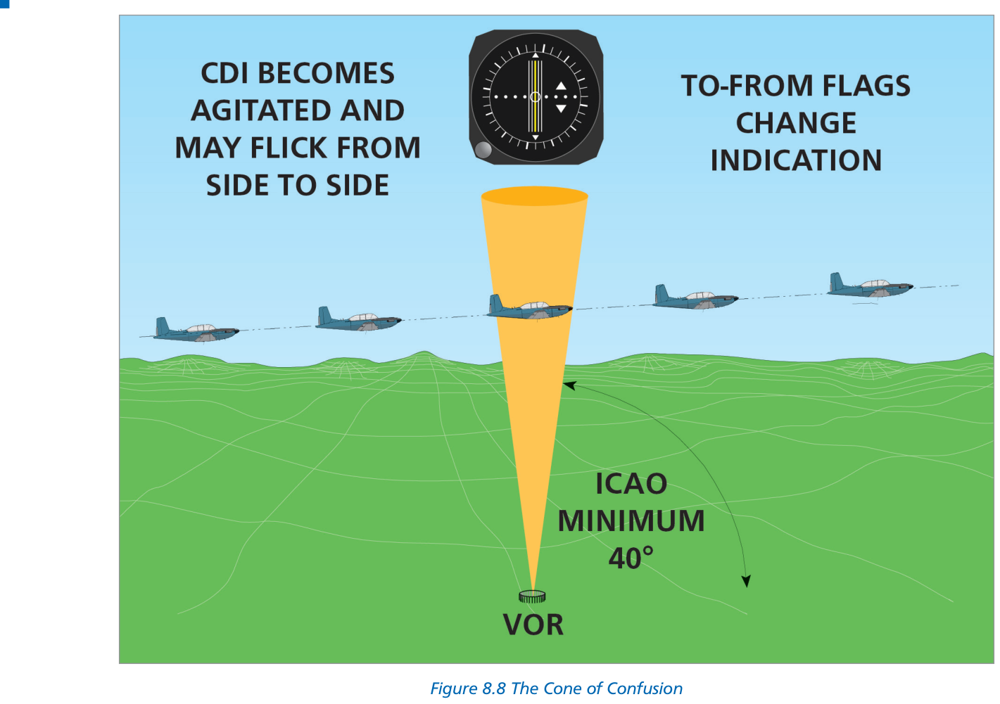
- OFF flag may appear on CDI/VOR indicator
- TO/FROM indicator alternates rapidly
- CDI needle oscillates / swings
- Extends approximately ±50° from vertical (antenna design dependent)
- Normal and temporary — do not attempt corrections while in the cone
2. CDI will settle after exiting the cone (typically within 1–2 minutes at normal speeds).
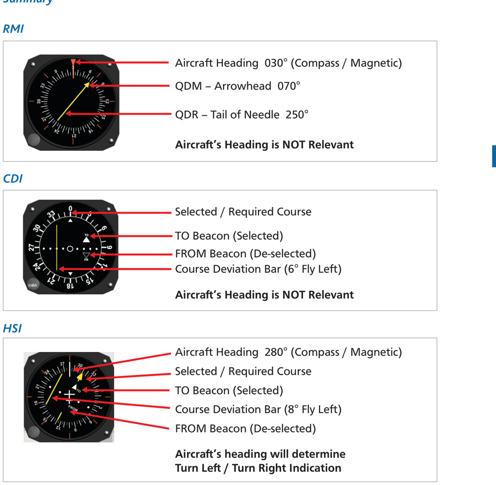
11. Cockpit Displays — CDI, RMI, HSI
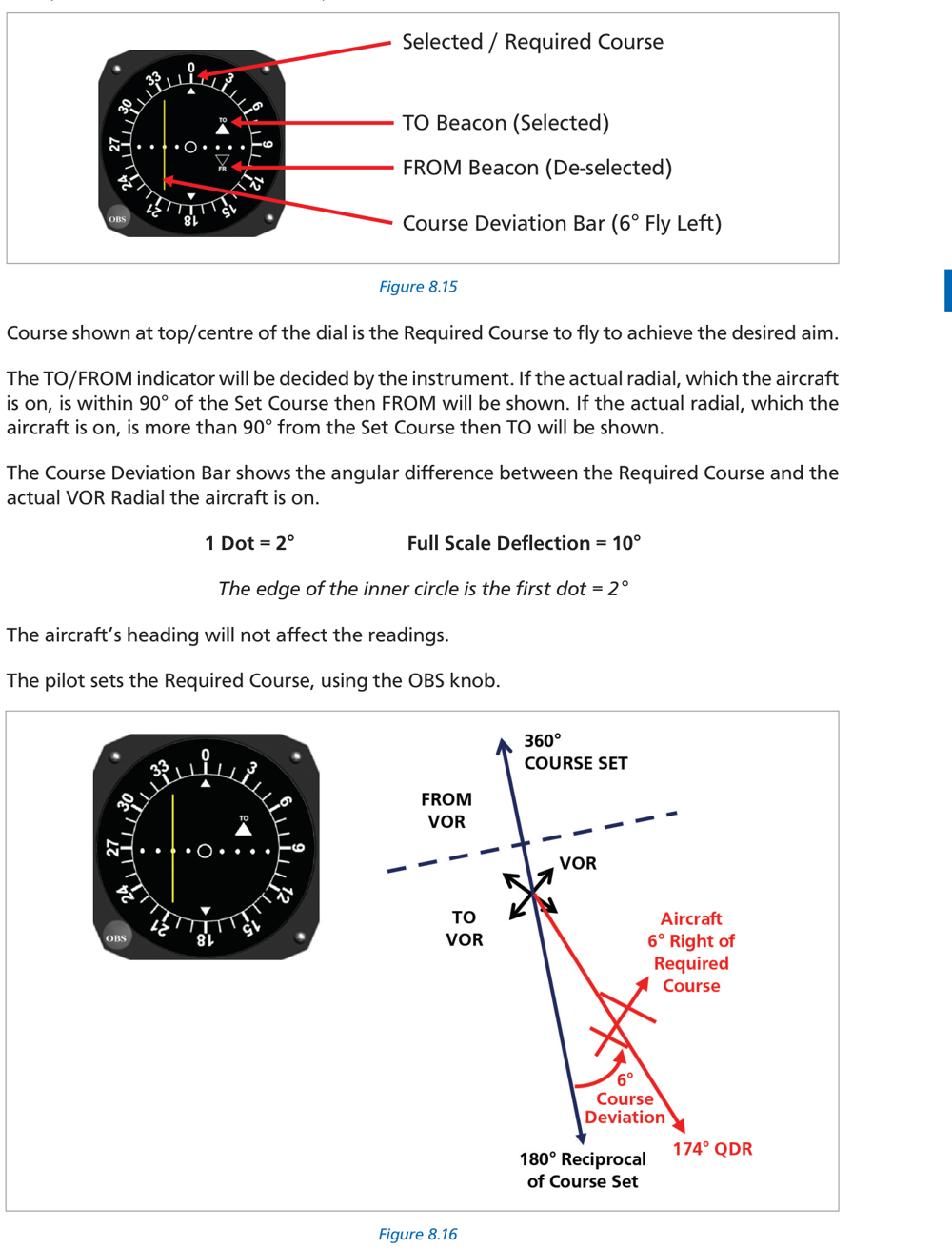
11.1 CDI — Course Deviation Indicator
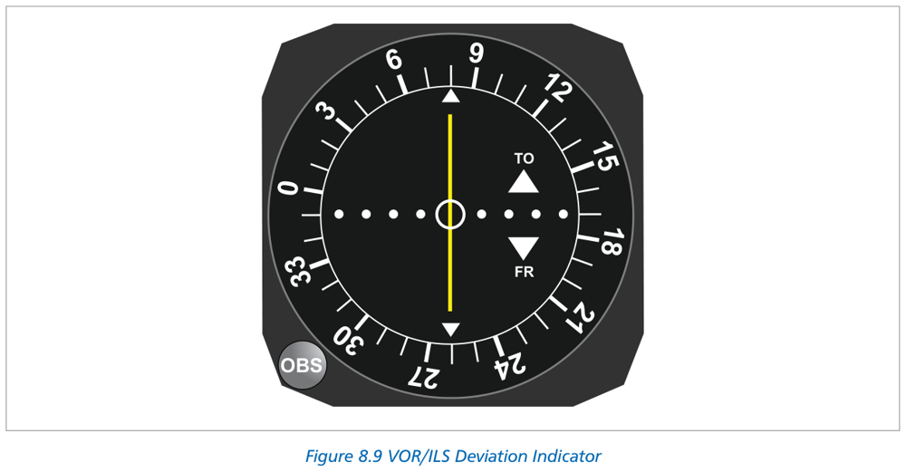
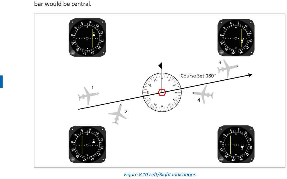
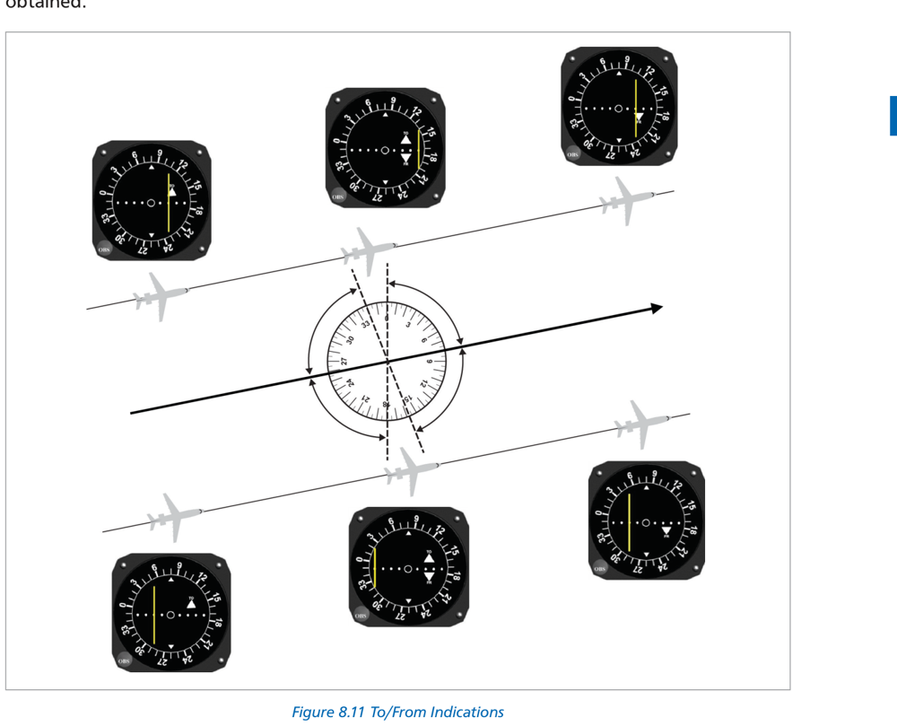
| Parameter | Value |
|---|---|
| Sensitivity | 2° per dot |
| Full Scale Deflection (FSD) | ±10° (= ±5 dots) |
| TO indication | QDM is within ±80° of OBS setting |
| FROM indication | QDR is within ±80° of OBS setting |
| OFF indication | OBS is ~90° away from QDM/QDR (ambiguous zone) |
Therefore aircraft is to the LEFT of the 329° course → CDI bar deflects RIGHT (fly right).
Deflection = 3° ÷ 2°/dot = 1.5 dots right.
11.2 RMI — Radio Magnetic Indicator
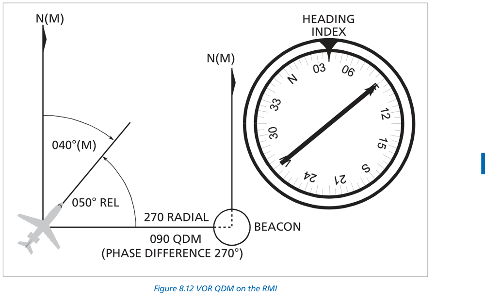
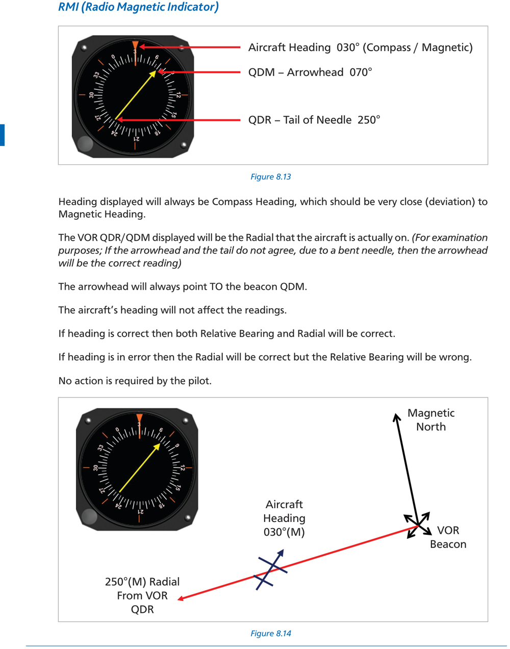
| Needle Part | Reading | Equivalent |
|---|---|---|
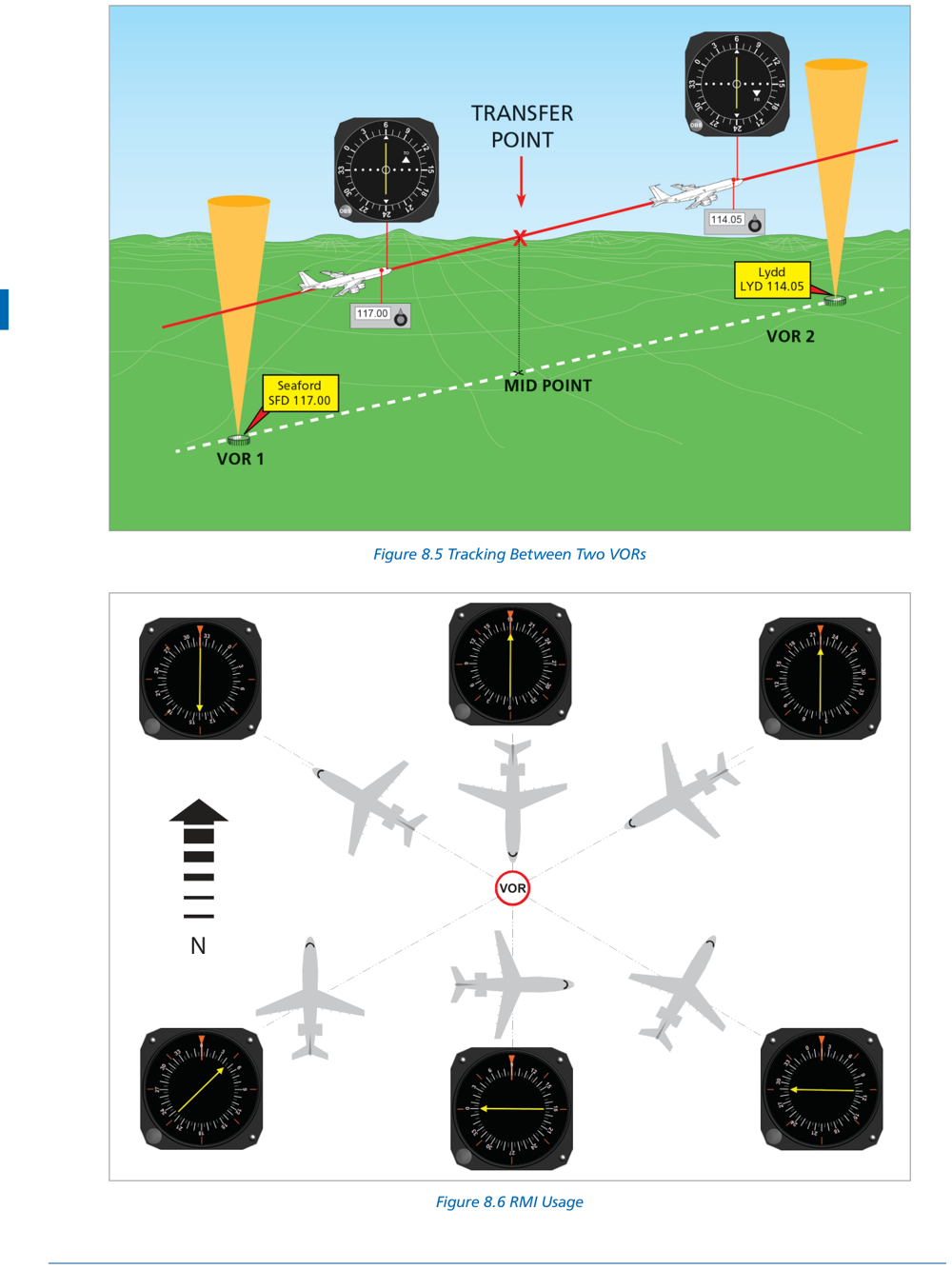
| Head (arrowhead) | Points TO the station | QDM — magnetic bearing TO station |
| Tail | Points AWAY from station | QDR — radial — magnetic bearing FROM station |
The RMI compass card rotates with aircraft heading, so the needle always reads magnetic bearings (not relative bearings).
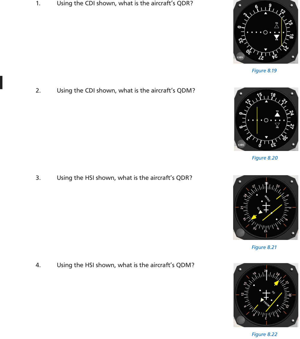
- Q1: Heading 360°, needle head at 071° → QDM = 071°, QDR = 251°
- Q2: Heading 090°, needle head at 159° → QDM = 159°, QDR = 339°
- Q3: Heading 220°, needle head at 345° → QDM = 345°, QDR = 165°
- Q4: Heading 270°, needle head at 063° → QDM = 063°, QDR = 243°
11.3 HSI — Horizontal Situation Indicator
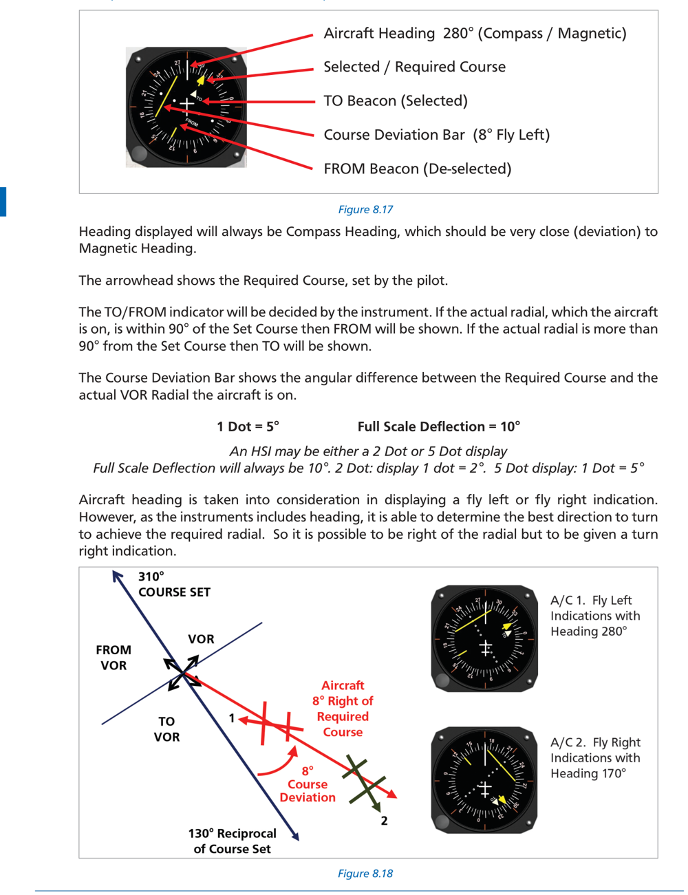
| Parameter | Standard HSI | Narrow-bar HSI |
|---|---|---|
| Sensitivity | 5° per dot | 2° per dot |
| Dots each side | 2 dots | 2 dots |
| FSD | ±10° | ±4° |
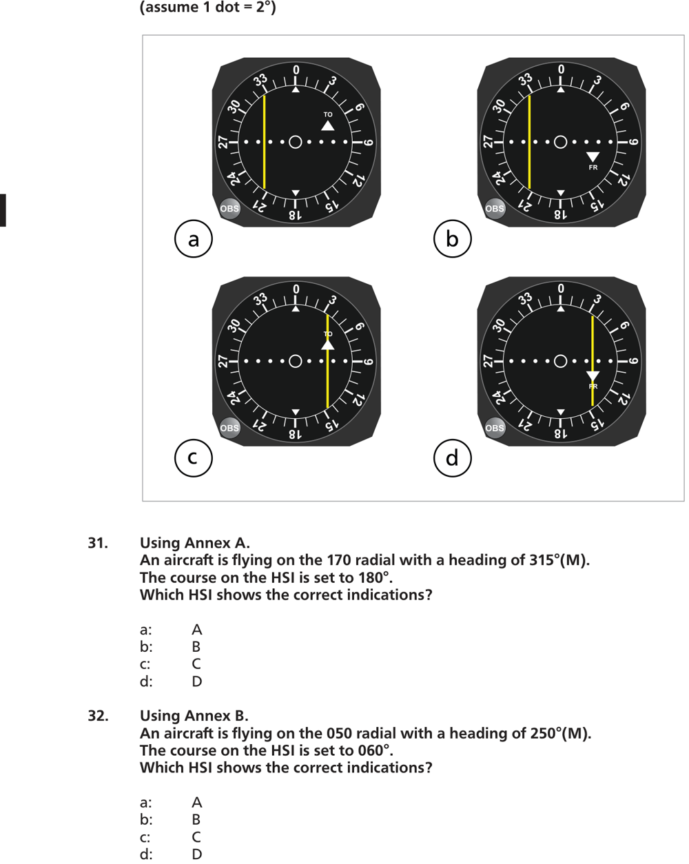
The HSI course pointer rotates with aircraft heading → the deviation bar always shows correct turn direction regardless of OBS setting. No CDI sense reversal.
12. In-Flight Procedures
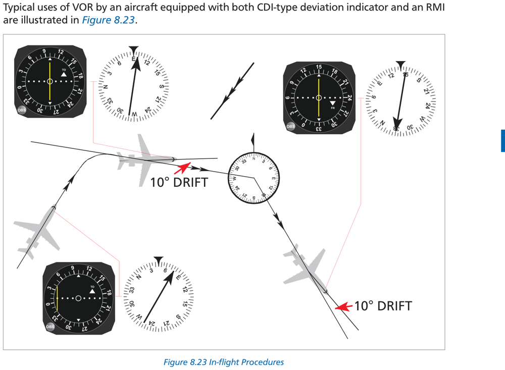
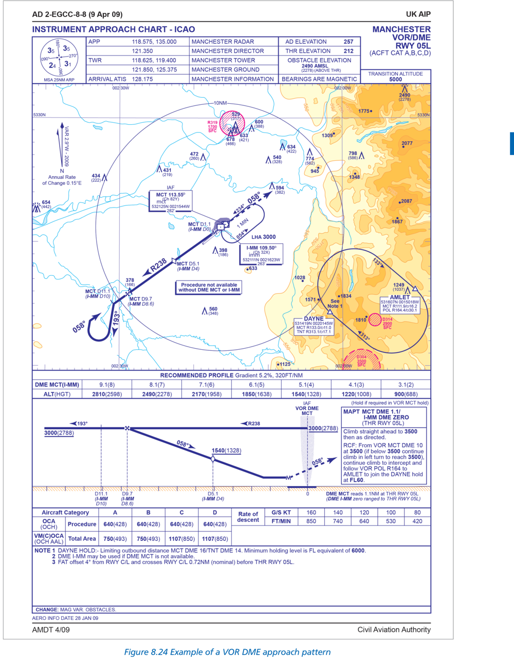
- Set OBS to desired outbound radial (e.g., 090° for east outbound)
- FROM flag appears
- Wind correction: CDI drifts right → turn right to correct (normal sense with FROM selected)
- Set OBS to inbound track (reciprocal of radial, e.g., 270° for inbound on 090° radial)
- TO flag appears
- CDI normal sense — fly toward the needle
- Primary: TO → FROM flag change
- CDI needle may swing briefly
- OFF flag may appear momentarily in cone of confusion
- Log time of station passage for flight planning
13. VOR Summary Table
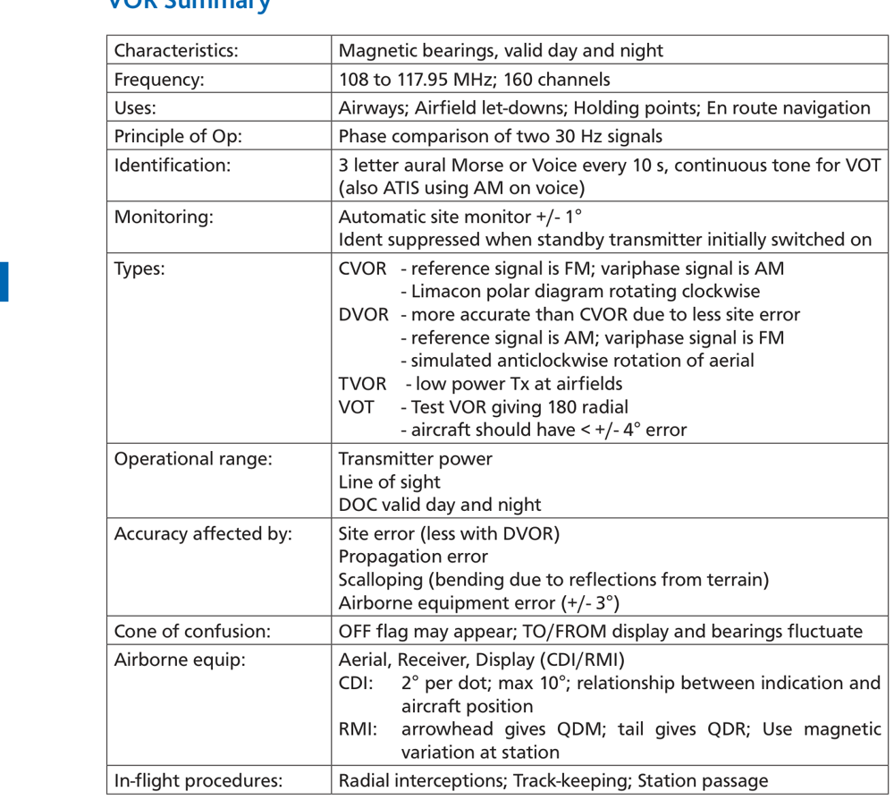
| Parameter | Value / Detail |
|---|---|
| Frequency band | 108.0 – 117.95 MHz (VHF) |
| Total channels | 160 (40 shared with ILS + 120 VOR only) |
| Emission designator | A9W |
| Principle | Phase comparison of two 30 Hz signals |
| Ident interval | 3-letter Morse every 10 s (1020 Hz tone) |
| Monitor trigger | ±1° bearing error → auto-shutdown |
| VOT tolerance | ±4° |
| Site error | ±1° |
| Total system accuracy | ±5° |
| DOC validity | Day AND night |
| LOS range formula | 1.25 × (√H1 + √H2) NM (H in feet) |
| CDI sensitivity | 2°/dot, FSD ±10° |
| HSI sensitivity | 5°/dot standard (FSD ±10°); 2°/dot narrow |
| Radial (QDR) | Magnetic bearing FROM VOR to aircraft |
| Variation applied at | VOR station (not aircraft) |
| Cone of confusion | ±50° from vertical — OFF flag, needle oscillates |
14. Practice Questions
VOR operates in the VHF band, 108.0–117.95 MHz. (a) = UHF military TACAN; (c) = NDB/ADF MF/LF band; (d) = DME UHF.
VOR uses phase comparison of two 30 Hz signals. The reference is omnidirectional (FM subcarrier); the variable rotates (AM on carrier). Their phase difference = radial.
A radial = QDR = magnetic bearing FROM VOR to aircraft. Aircraft on the 090° radial is due east of the station.
Range = 1.25 × (√3600 + √100) = 1.25 × (60 + 10) = 1.25 × 70 = 87.5 NM.
A VOT (VOR Test facility) radiates a continuous Morse dots tone. Used on the ground to verify aircraft VOR receiver accuracy. Aircraft must read 000°(±4°) FROM or 180°(±4°) TO.
VOT maximum permissible error = ±4°. Exceeding this requires equipment servicing before use.
VOR DOC is valid day AND night. VHF is immune to skywave propagation. Contrast with NDB/ADF whose DOC is day only.
Total VOR accuracy = ±5°: site error ±1° + propagation/scalloping ±1° + airborne equipment ±3° (RSS combination).
Overhead VOR = cone of confusion: OFF flag may appear, TO/FROM alternates rapidly, CDI needle oscillates. Normal and temporary.
CDI sensitivity = 2° per dot. Full scale = 5 dots × 2° = ±10°.
CDI FSD = ±10° (5 dots × 2°/dot).
RMI: arrowhead (head) = QDM = bearing TO station. Tail = QDR = radial = bearing FROM station.
DVOR uses a ring of 48 antennas switched electronically. Doppler effect generates FM variable signal. Less susceptible to site errors from terrain/structures.
QDR = 090°M. Apply variation at VOR: 090° + 6° (East) = 096°T. (True = Magnetic + East variation)
Max spacing = (half-width × 60) / error = (5 × 60) / 5 × 2 = 600/5 = 120 NM. (Using the standard 600/error_degrees formula.)
Max spacing = 600 / 5.5 ≈ 109 NM.
108–112 MHz: even tenths = VOR (40 channels); odd tenths = ILS Localiser (40 channels).
Total VOR channels = 40 (shared, 108–112) + 120 (VOR only, 112–118) = 160.
Track = Heading + Starboard drift = 287° + 14° = 301°. QDR = track when flying outbound from VOR.
Phase difference = radial = QDR = Track = 287° + 14° = 301°.
TO flag illuminates when QDM (bearing to station) is within ±80° of the OBS setting. Not dependent on aircraft heading — geometry only.
OBS 329° TO means desired radial = 149°. Aircraft is on 152° — 3° clockwise of 149° → aircraft is LEFT of the 329° inbound course → bar deflects RIGHT (fly right). 3° ÷ 2°/dot = 1.5 dots.
Exact: 100 × sin(5°) = 100 × 0.0872 ≈ 8.7 NM. Using 1:60: 100 × 5/60 ≈ 8.3 NM.
For VOR, variation is applied at the VOR station. Contrast with NDB/ADF: variation applied at the aircraft.
QDR (radial) = 045° → RMI tail = 045°. RMI head = QDM = 225° (reciprocal). Answer: head 225°, tail 045°.
Standard HSI: 5°/dot × 2 dots = 10° FSD.
VOR Morse ident is transmitted every 10 seconds.
Auto-monitor: if error >±1° → station shuts down or switches to standby. Ident suppressed for 30 s. Never use VOR without ident.
VORTAC: civil aircraft receive VOR azimuth + DME distance (via TACAN DME on paired freq). Military: TACAN bearing + DME.
VOR = A9W. A = AM DSB; 9 = composite signal; W = combination of telephony, telegraphy and navigation.
5°/dot HSI. Aircraft 4° RIGHT of course → bar deflects LEFT (fly left to intercept). Magnitude = 4° ÷ 5°/dot = 0.8 dots left = less than 1 dot LEFT.
DVOR: AM carrier = reference; electronically switched 48-antenna ring generates FM variable via Doppler effect. CVOR: FM subcarrier = reference; AM rotating limàcon = variable.
Aircraft west of VOR flying east (inbound). QDM = 090°. OBS = 090°. QDM is within 80° of OBS → TO.
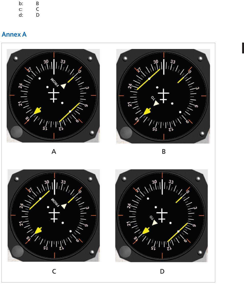
Annex A — HSI Diagrams (Q31)
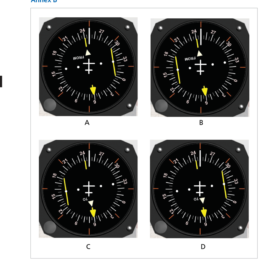
Annex B — HSI Diagrams (Q32)
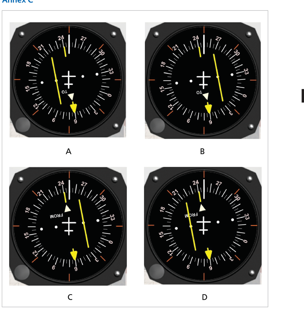
Annex C — HSI Diagrams (Q33)
Additional Question Diagrams
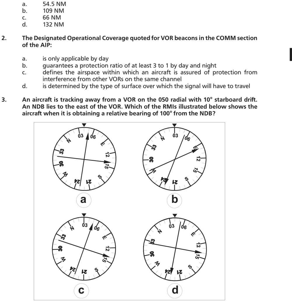
Q3 — RMI Options
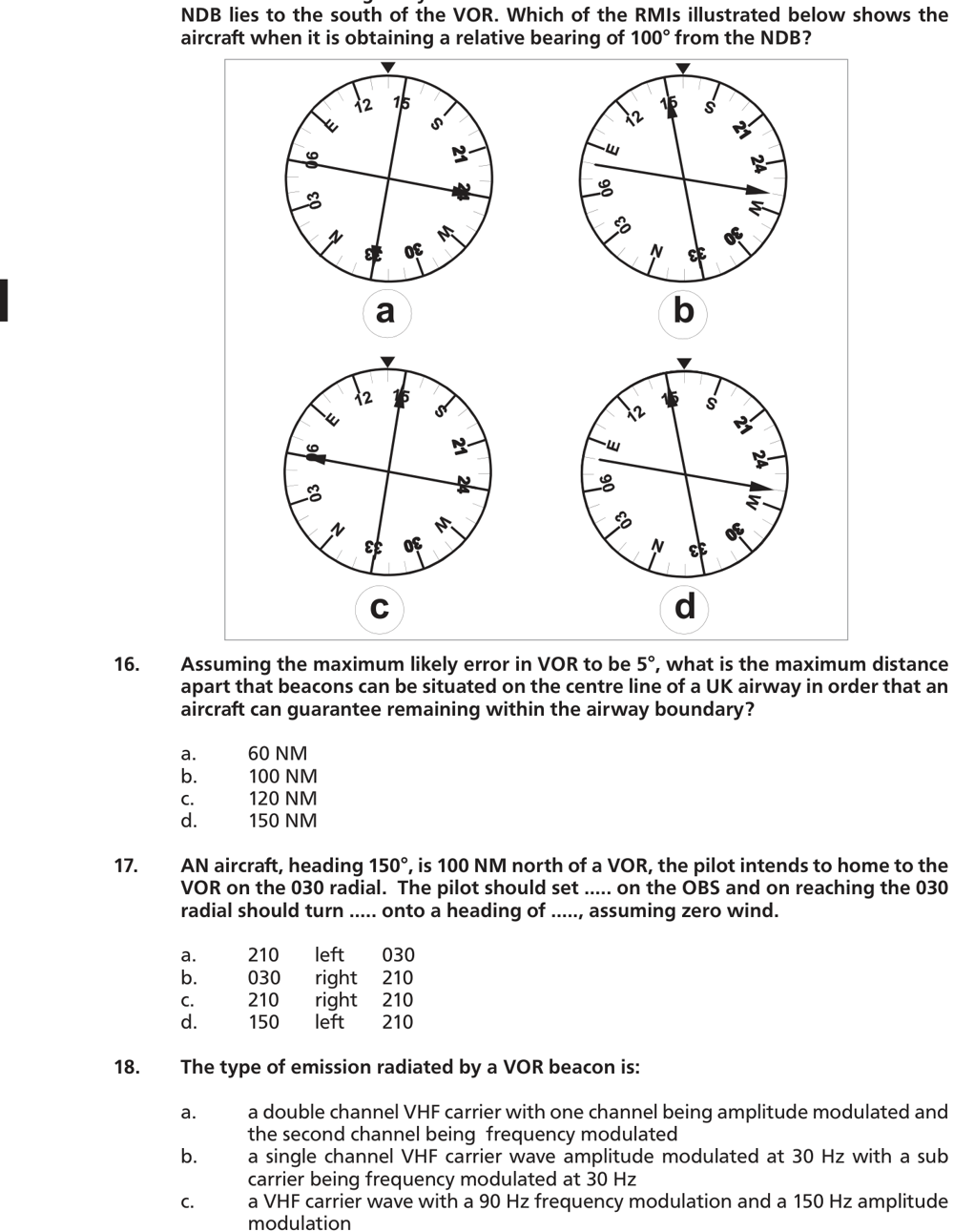
Q15 — RMI Options
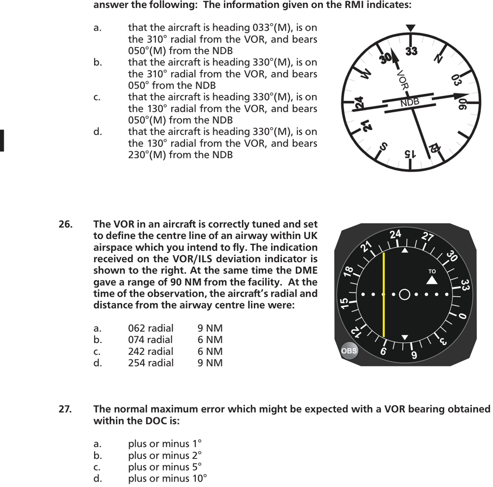
Q25 (RMI) and Q26 (CDI)
Q28 — RMI Options
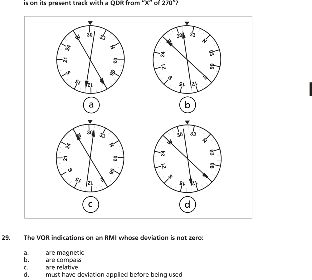
Q30 — CDI Options
Chapter 8 — VOR (VHF Omnidirectional Range)
Ghost Aviator | www.ghostaviator.com
For personal study use only. Not to be reproduced without permission.
Reinforce Chapter 8: VOR
Test your knowledge and practice actual exam questions for Radio Navigation.