13
RADIO NAV — CHAPTER 13 · NOTES
Airborne Weather Radar
by Ghost Aviator
Ghost Aviator
www.ghostaviator.com
Ghost Aviator
www.ghostaviator.com
Ghost Aviator
DGCA CPL / ATPL Study Notes • Radio Navigation • Ch 13
✈ Chapter 13: Airborne Weather Radar
AWR — Weather Detection & Ground Mapping
📋 Contents
1. Introduction & Components 2. AWR Functions 3. Principle of Operation 4. Weather Depiction & Colours 5. Monochrome Control Unit 6. Mapping Operation 7. Weather Operation 8. Colour AWR Controls 9. AWR Summary 10. Practice Questions (11 Q)1. Introduction & Components
Airborne Weather Radar (AWR) provides pilots with weather and navigation information ahead of the aircraft. It requires pilot interpretation — its usefulness depends on operator skill. It can display on a dedicated unit or on the EFIS navigation display (ND).
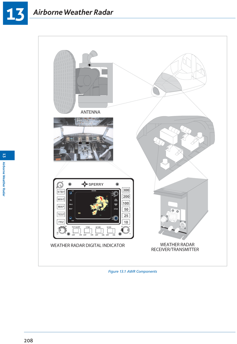
Fig 13.1: AWR components — Tx/Rx, antenna, indicator, control unit
📡 AWR Components
- Transmitter/Receiver: generates and detects microwave pulses
- Antenna: attitude-stabilised in pitch and roll; parabolic or flat plate
- Indicator: PPI display (monochrome or colour)
- Control Unit: range, tilt, function, gain controls
2. AWR Functions
📡 Main AWR Functions
- Detect size of water droplets → identify areas of turbulence within clouds
- Determine height of cloud tops by tilting beam up/down
- Map terrain below aircraft for navigation and high ground avoidance
- Provide position fix (range and bearing) from prominent terrain features
3. Principle of Operation
📡 AWR — Primary Radar Principles
- Echo principle: determines range of targets
- Searchlight principle: determines relative bearing of targets
- Range shown on display is slant range — use Pythagoras to find ground range
- Antenna is attitude-stabilised in pitch and roll — if stabilisation fails display becomes lopsided
AWR Frequency
📡 Why 9375 MHz (3.2 cm)?
- Optimum for detecting large water droplets and wet hail (~3 cm diameter) associated with severe turbulence
- Typical frequency: 9375 MHz ±30 MHz (SHF band)
- λ = 300/9375 = 3.2 cm
- Higher frequency → returns from smaller droplets (clutter); Lower frequency → insufficient returns
- Wavelengths >10 cm produce few weather returns
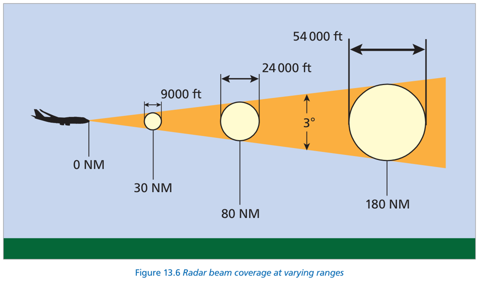
Fig 13.6: Radar beam coverage at varying ranges — 3° beam width, range rings at 30/80/180 NM
Radar Beams
📡 Beam Types
| Beam | Shape | Used For | Range |
|---|---|---|---|
| Pencil/Conical | 3°–5° width | Weather depiction + long range mapping | >60 NM (up to ~150 NM) |
| Cosecant² / Fan-shaped | 85° deep, 3.5° azimuth | Short range ground mapping | 15–70 NM |
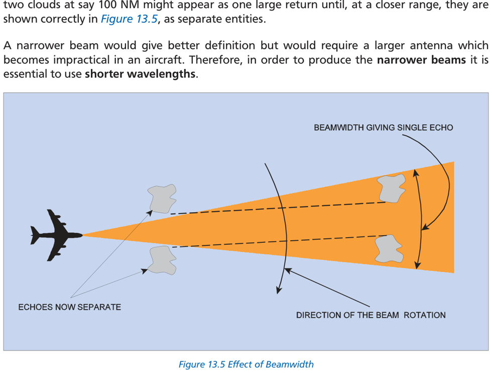
Fig 13.5: Effect of beamwidth — two clouds at 100 NM appear as one; separate correctly at closer range
⚡ Water/Ice in Radome
Radar energy absorbed by water/ice in the radome (like a microwave oven) → weaker forward transmission → degraded performance. Radome must be kept dry and ice-free.
4. Weather Depiction & Colours
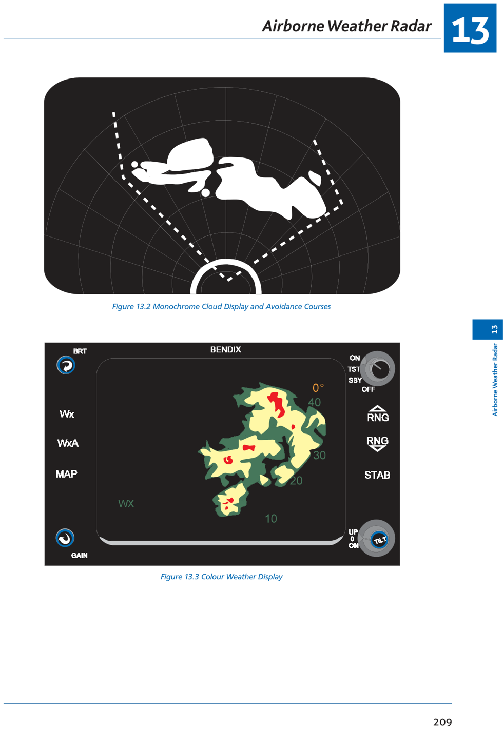
Fig 13.2: Monochrome cloud display + avoidance courses | Fig 13.3: Colour weather display
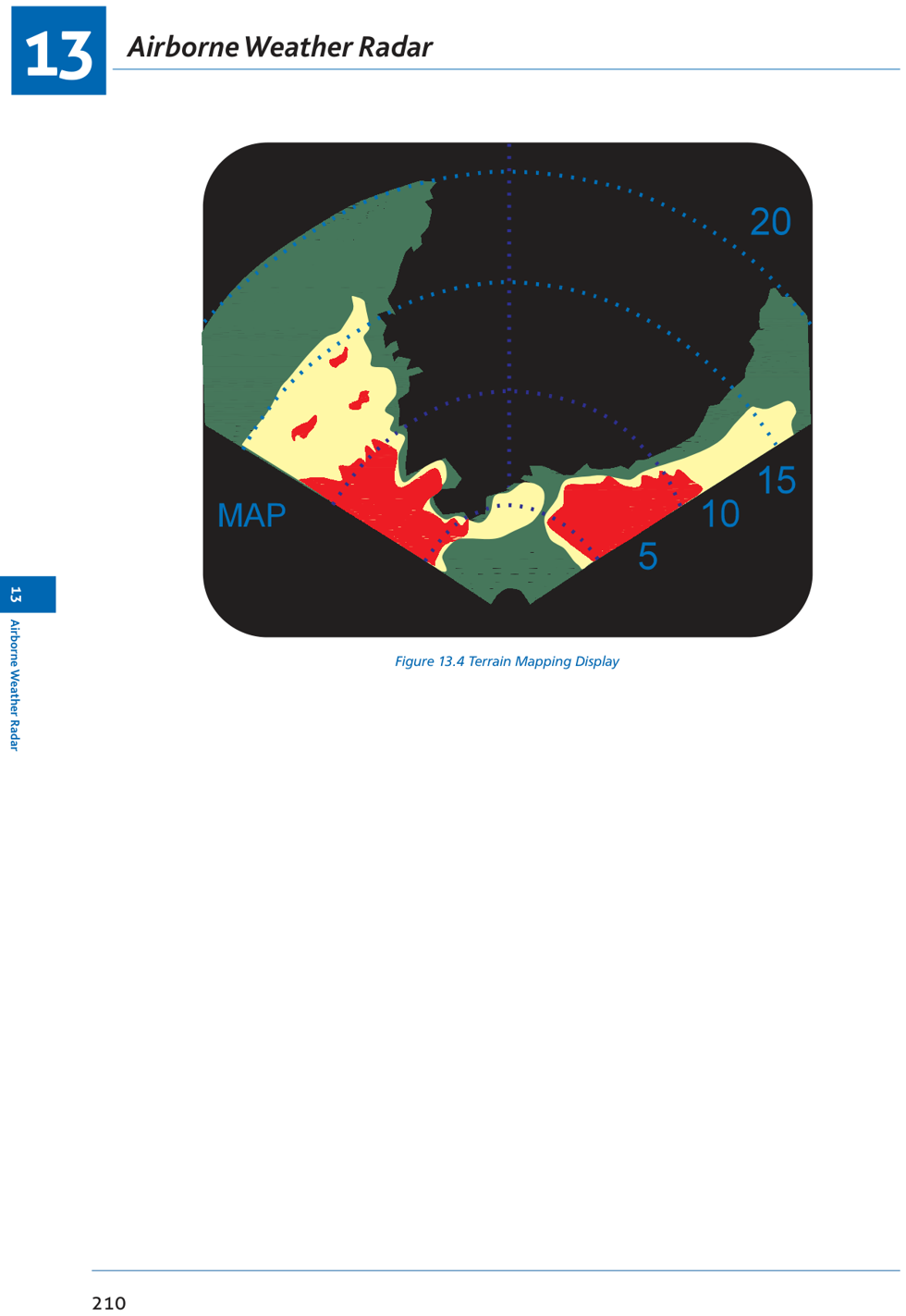
Fig 13.4: Terrain mapping display — coastlines and built-up areas give bright returns
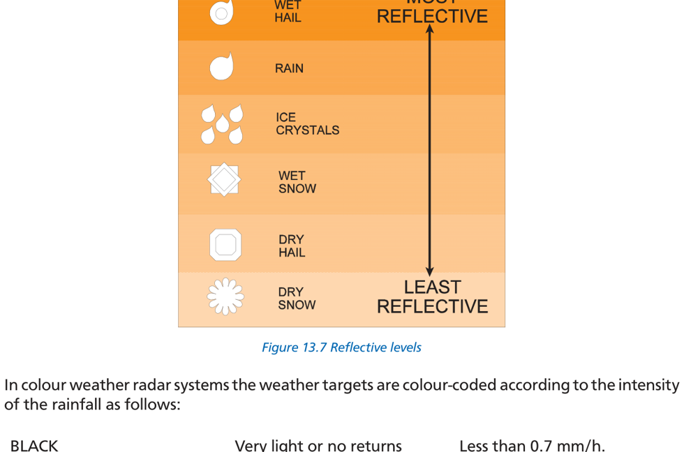
Fig 13.7: Reflective levels — different precipitation types give different radar returns
📡 Colour Coding — Weather Mode
On colour systems WITHOUT magenta: RED areas may have a CYCLIC function (RED/BLACK alternating) to draw attention.
| Colour | Rainfall Rate | Meaning |
|---|---|---|
| BLACK | <0.7 mm/h | Very light or no returns |
| GREEN | 0.7–4 mm/h | Light returns |
| YELLOW | 4–12 mm/h | Medium returns |
| RED | >12 mm/h | Strong returns |
| MAGENTA | Turbulence intensity | Severe turbulence |
📡 Colour Coding — Mapping Mode
| Colour | Meaning |
|---|---|
| GREEN | Light ground returns |
| YELLOW | Medium ground returns |
| RED | Heavy ground returns |
Turbulence Indicators
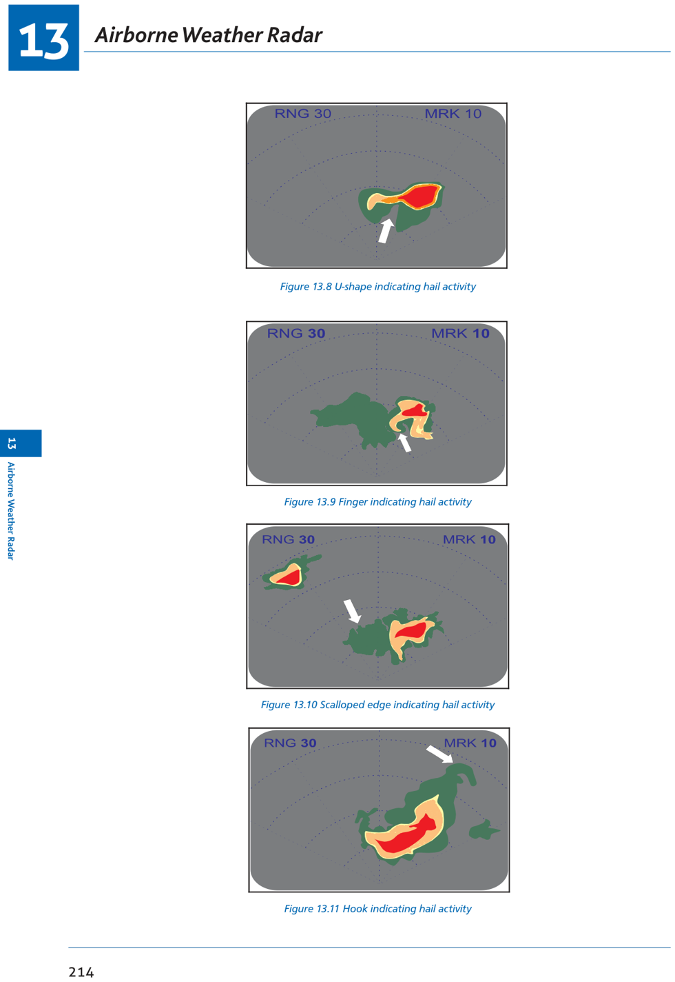
Fig 13.8–13.11: Turbulence shapes — U-shape, Finger, Scalloped edge, Hook — all indicate hail/severe turbulence
⚠ Areas to Avoid on AWR Display
- Where colour zones are closest together (steepest rainfall gradient)
- U-shapes — hail activity
- Fingers — hail activity
- Scalloped edges — hail activity
- Hooks — hail activity
5. Monochrome Control Unit
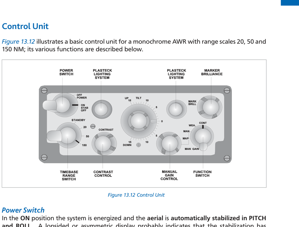
Fig 13.12: AWR monochrome control unit — power, range, tilt, function switches
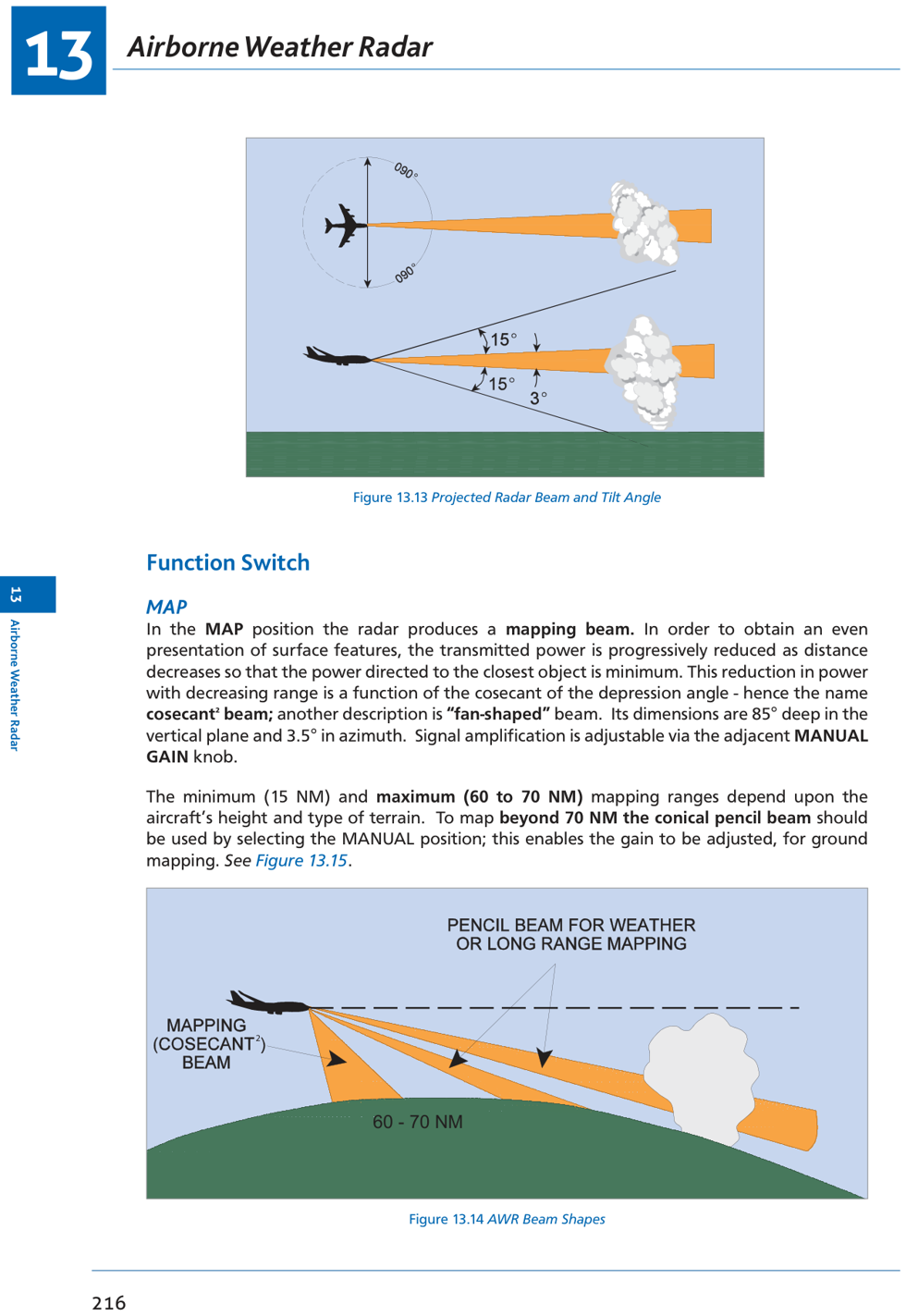
Fig 13.13: Projected radar beam and tilt angle | Fig 13.14: Pencil and fan-shaped beam shapes
📡 Control Unit Functions
| Control | Position | Effect |
|---|---|---|
| Power / Stab | ON (Stab On) | System energized; antenna attitude-stabilised in pitch & roll |
| STAB OFF | Scanner locked to aircraft axes — display lopsided during manoeuvres | |
| Range | STANDBY | Equipment ready, transmitter OFF. Maintain on ground until clear of personnel |
| Range selections | Energizes transmitter; up to 150 NM practical max | |
| Tilt | ±15° | Tilts beam up (+) or down (−). Tilt up for increased range or lower altitude. Sweep ±90° (60° typical) |
| MAP | Cosecant² beam | Fan-shaped beam; use up to 60–70 NM. Manual gain operative |
| MAN | Pencil beam | Manual gain; map >60 NM; weather/navigation 70–150 NM |
| WEA | Pencil beam | Normal weather observation. AGC/Swept Gain automatic (operative up to ~25 NM) — manual gain INOPERATIVE |
| CONT | Contour | Highlights dangerous rainfall gradient; Swept Gain also operative; darker colour = dangerous areas |
⚡ AGC / Swept Gain / STC
Automatic Gain Control decreases receiver gain for nearer echoes → ensures a small nearby cloud does NOT appear brighter than a larger distant cloud. Operates up to ~25 NM. Makes ALL clouds up to 25 NM directly comparable.
6. Mapping Operation
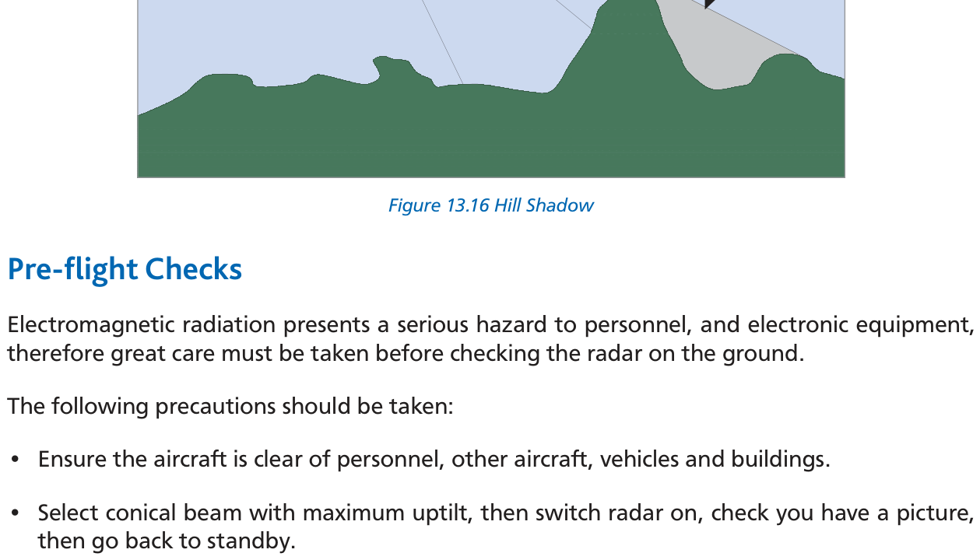
Fig 13.16: Hill shadow — radar shadow behind mountains may give false impression of water/lakes
📡 Ground Mapping Guide
- MAP (cosecant²): use up to 60–70 NM; tilt beam down for best presentation
- MAN (pencil beam): use for mapping beyond 70 NM
- Bright returns: coastlines, built-up areas, skyscrapers, bridges, power stations
- Weak returns: calm sea, fine sand, flat terrain
- Ice has jagged edges (reflects); snow is a poor reflector and masks ground features
- Hill shadow: mountains create radar shadow → may appear as a false lake
⚠ Pre-flight Radar Check Precautions
- Ensure aircraft is clear of personnel, other aircraft, vehicles and buildings
- Select conical beam with maximum uptilt, switch on briefly, check for picture, return to STANDBY
- Electromagnetic radiation is a health hazard — never point operating radar at personnel
7. Weather Operation
✓ Thunderstorm Avoidance Procedure
- Select maximum range to detect weather in good time; adjust tilt to remove ground returns
- If storm is extensive, make early track adjustment in consultation with ATC
- As clouds approach, select lower ranges + CONT; determine best track to avoid turbulence
- Ensure short-term heading changes steer AWAY from worst areas
- Constantly switch between short/medium/long ranges to maintain complete storm picture
⚠ AWR Limitations
- Shadow area: Heavy rain blocks radar waves → area behind heavy rain may conceal severe weather
- Too high tilt: A thunderstorm may not be detected if tilt is set too high
- AWR does NOT detect Clear Air Turbulence (CAT)
- Height ring: In older AWR with dish antenna, vertical overspill gives a ‘height ring’ on display — indicates serviceability and roughly the aircraft's height
8. Colour AWR Controls
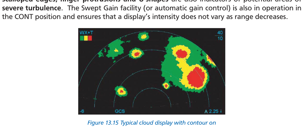
Fig 13.15: Cloud display with CONT (contour) on — darker areas indicate dangerous turbulence
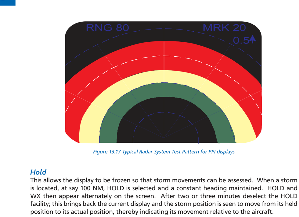
Fig 13.17: Radar test pattern — used for pre-flight serviceability check
📡 Additional Colour AWR Features
| Function | Description |
|---|---|
| Wx, Wx+T, Wx(var) | Weather / Weather + Turbulence / Weather with variable gain |
| WxA | Weather Alert — flashing display of turbulence areas |
| TEST | Displays colour pattern for pre-flight serviceability check |
| HOLD | Freezes display to assess storm movement. After 2–3 min, deselect to see storm displacement |
| TGT ALERT | Alerts pilot of contour-strength storm within 60–160 NM and ±15° of heading. Flashes TGT symbol. |
| FAULT | Flashes on screen if power or transmitter failure detected |
9. AWR Summary
| Parameter | Detail |
|---|---|
| Type | Primary radar |
| Frequency | 9375 MHz (±30 MHz), SHF, λ=3.2 cm |
| Principle | Echo (range) + searchlight (bearing). Range shown is slant range. |
| Pencil beam | 3°–5°; weather + long range mapping (>60 NM) |
| Fan beam (MAP) | Cosecant²; short range mapping up to 60–70 NM |
| Antenna stabilisation | Pitch and roll; lopsided display = stab failure |
| Tilt | ±15°; UP for longer range/lower altitude |
| Weather colours | Black → Green → Yellow → Red → Magenta |
| Turbulence warning shapes | U-shapes, Fingers, Scalloped edges, Hooks |
| AGC range | Operates up to ~25 NM in WEA/CONT mode |
| Max practical range | ~150 NM |
| AWR does NOT detect | Clear Air Turbulence (CAT) |
10. Practice Questions
Q1. A frequency used by airborne weather radar is:
(a) 8800 MHz
(b) 9.375 GHz
(c) 93.75 GHz
(d) 1213 MHz
Answer: (b)
AWR frequency = 9375 MHz = 9.375 GHz (SHF band). This gives the best returns from large water droplets (~3 cm) associated with severe turbulence.
AWR frequency = 9375 MHz = 9.375 GHz (SHF band). This gives the best returns from large water droplets (~3 cm) associated with severe turbulence.
Q2. AWR required to detect targets up to 200 NM. Maximum PRR:
(a) 405 pps
(b) 810 pps
(c) 1500 pps
(d) 750 pps
Answer: (a)
Max PRF = 81,000 / 200 = 405 pps.
Max PRF = 81,000 / 200 = 405 pps.
Q3. Weather beam preferred over fan-shaped beam for mapping in excess of ___ NM:
(a) 20–25
(b) 60–70
(c) 100–150
(d) 150–200
Answer: (b)
Fan-shaped (cosecant²) beam used up to 60–70 NM. Beyond that, use pencil (weather/MAN) beam.
Fan-shaped (cosecant²) beam used up to 60–70 NM. Beyond that, use pencil (weather/MAN) beam.
Q4. AWR is an example of ___ radar at frequency ___ in the ___ band:
(a) primary, 8800 MHz, SHF
(b) secondary, 9.375 MHz, UHF
(c) secondary, 9375 MHz, SHF
(d) primary, 9375 MHz, SHF
Answer: (d)
AWR is primary radar at 9375 MHz in the SHF band.
AWR is primary radar at 9375 MHz in the SHF band.
Q5. Correct colour sequence as returns get stronger:
(a) red, yellow, green
(b) yellow, green, red
(c) green, yellow, red
(d) red, green, yellow
Answer: (c)
Colour sequence in order of increasing return strength: Black → Green → Yellow → Red → Magenta.
Colour sequence in order of increasing return strength: Black → Green → Yellow → Red → Magenta.
Q6. A false indication of water may be given by AWR when:
(a) flying over land with Land/Sea switch in Sea position
(b) flying over mountainous terrain
(c) cloud/precipitation between aircraft and cloud target
(d) using mapping beam beyond 50 NM
Answer: (b)
Hill shadows created by mountainous terrain can give a false impression of water (lakes) on the AWR display.
Hill shadows created by mountainous terrain can give a false impression of water (lakes) on the AWR display.
Q7. AWR operates at 9375 MHz because:
(a) 8800 MHz gives best returns from all precipitation
(b) 13300 MHz used
(c) 9375 MHz gives best returns from rainfall associated with Cb
(d) 9.375 GHz best for detecting aircraft
Answer: (c)
9375 MHz gives the best returns from large water droplets and wet hail found in convective clouds (Cb) associated with severe turbulence.
9375 MHz gives the best returns from large water droplets and wet hail found in convective clouds (Cb) associated with severe turbulence.
Q8. Mapping mode of AWR utilizes:
(a) pencil beam from 70 NM to 150 NM
(b) cosecant² beam effective to 150 NM
(c) pencil beam max range 70 NM
(d) cosecant² beam effective 50 NM to 70 NM
Answer: (a)
MAP (cosecant²) is used up to 60–70 NM. For mapping beyond 70 NM, select MAN to use the pencil/weather beam from 70 NM to 150 NM.
MAP (cosecant²) is used up to 60–70 NM. For mapping beyond 70 NM, select MAN to use the pencil/weather beam from 70 NM to 150 NM.
Q9. AWR uses 9 GHz because the wavelength gives reflections only from:
(a) short wavelength produces higher frequency returns
(b) reflects from cloud water droplets of all sizes
(c) wavelength gives reflections only from the larger water droplets
(d) frequency penetrates clouds for good mapping
Answer: (c)
3.2 cm wavelength is comparable to the size of large water droplets and wet hail (~3 cm). This gives reflections from dangerous precipitation while ignoring smaller harmless droplets.
3.2 cm wavelength is comparable to the size of large water droplets and wet hail (~3 cm). This gives reflections from dangerous precipitation while ignoring smaller harmless droplets.
Q10. AWR antenna is stabilised:
(a) in pitch, roll and yaw
(b) in pitch and roll
(c) in pitch and roll whether stab on or off
(d) in pitch and roll only at 0° tilt
Answer: (b)
AWR antenna is stabilised in pitch and roll. STAB OFF locks scanner to aircraft axes — display becomes lopsided during manoeuvres.
AWR antenna is stabilised in pitch and roll. STAB OFF locks scanner to aircraft axes — display becomes lopsided during manoeuvres.
Q11. AWR colours: very light/no returns ___, light ___, medium ___, strong ___:
(a) black, yellow, green, magenta
(b) black, green, yellow, magenta
(c) grey, green, yellow, red
(d) black, green, yellow, red
Answer: (d)
Colour sequence: Black (very light) → Green (light) → Yellow (medium) → Red (strong) → Magenta (turbulence).
Colour sequence: Black (very light) → Green (light) → Yellow (medium) → Red (strong) → Magenta (turbulence).
DGCA CPL/ATPL Radio Navigation Study Notes
Chapter 13 — Airborne Weather Radar
Ghost Aviator | www.ghostaviator.com
For personal study use only.
Chapter 13 — Airborne Weather Radar
Ghost Aviator | www.ghostaviator.com
For personal study use only.
Study Radio Nav with other student pilots
Join the free Radio Nav group on Telegram. Stuck on a doubt? Type /q and your question, and get an answer from Ghost Aviator's notes.
LIVE BATCH
Study Radio Navigation live with the Captain
Small batch of 10 · live doubt-clearing · 4–6 weeks · ₹12,999 ₹7,999
Reinforce Chapter 13: Airborne Weather Radar
Test your knowledge and practice actual exam questions for Radio Navigation.
Planning your Pilot Training in 2026?
Calculate exact flying hours, DGCA exam fees, and living costs with our interactive calculator.