Air Data Computer
by Ghost Aviator
Table of Contents
1. Introduction – The Air Data System (ADS)
In many modern large aircraft, conventional pressure instruments (altitude, airspeed, Mach number) are replaced by indicators driven by a central computer — the Air Data Computer (ADC). Together with sensors and displays, it forms the Air Data System (ADS).
ADS Components
- Pitot pressure sensor
- Static pressure sensor
- Total Air Temperature (TAT) probe
- Power supply
- The ADC unit itself
- Display instruments
Standard ADS Instrument Outputs
Additional outputs: Total Air Temperature (TAT), Static Air Temperature (SAT), True Airspeed (TAS).
Configuration Module
Because many aircraft types may use the same basic ADC, a Configuration Module is used to integrate it into each specific aircraft. This module is calibrated for differences in probe positioning efficiency to obtain the most accurate indications possible.
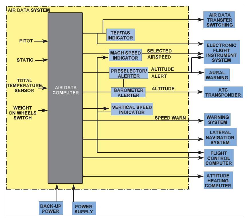
The ADS outputs are essential to the AFCS (Automatic Flight Control System) and also feed: altitude transponder, flight data recorder, navigation computer, and other systems.
2. Pitot-Static System and Redundancy
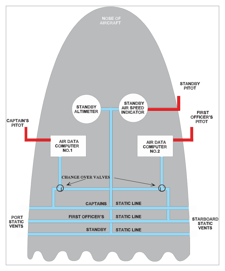
A typical aircraft has identical instrument sets on the Captain's and First Officer's panels. Each set connects to one of two independent ADCs fed from independent pitot and static sources that can be cross-connected.
Standby Instruments
In addition to ADC-fed instruments, there is always:
- A standby barometric altimeter — fed directly from an independent pitot-static source
- A standby airspeed indicator — fed directly from the same independent source
Each of the three independent pitot-static systems uses cross-coupled static vents on each side of the fuselage to reduce error from sideslip or yaw.
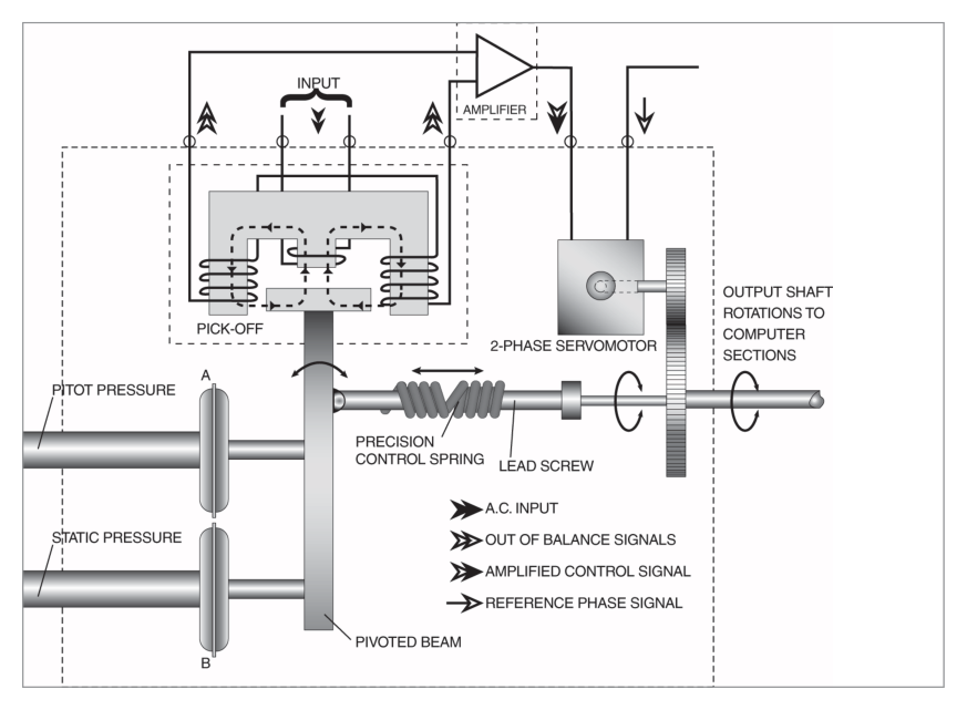
3. Air Data Computer – Analogue and Digital Types
3.1 Analogue ADC
Uses continuous physical variables (voltage, pressure, shaft rotation) to represent and transmit measurements. A Pressure Transducer converts the pressure inputs to shaft rotation via a 2-phase servomotor connected to a CX synchro. The analogue ADC is internally divided into modules:
- Altitude module
- Computed Airspeed (CAS) module
- Mach Speed module
- True Airspeed (TAS) module
- Rate of Climb module (using data from altitude module)
3.2 Digital ADC
Uses digital (binary) data for assessment and transmission. Analogue-to-Digital Converters (ADCs) at the input side convert pressure, temperature, and AOA measurements from analogue to digital form for internal processing and onward transmission to flight deck displays.
flowchart LR
    A["Pitot Pressure"] --> C["ADC"]
    B["Static Pressure"] --> C
    T["TAT Probe"] --> C
    AOA["AOA (some types)"] --> C
    C --> D["Altitude"]
    C --> E["Airspeed (CAS)"]
    C --> F["Mach Number"]
    C --> G["TAS"]
    C --> H["Vertical Speed"]
    C --> I["TAT / SAT"]
    C --> J["AFCS / FDR / XPDR / Nav Computer"]
4. System Redundancy
Redundancy is provided through:
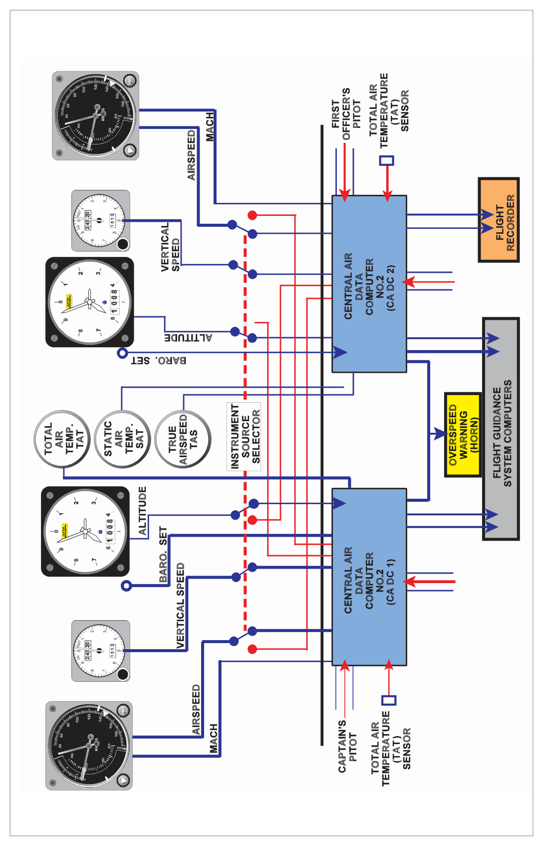
- Change-over cocks — permit an alternative static source to connect to the computer.
- Electrical switching — Captain's instruments can be fed from the First Officer's ADC and vice versa.
- Mixed sourcing — in some aircraft, ADC outputs are mixed to both sides of the panel, reducing the risk of an undetected malfunction.
- Standby instruments — available for total ADC failure due to power loss.
5. Failure Warning
A comparison monitor can be incorporated to automatically compare the outputs of both ADCs and warn the pilot of malfunction. With purely mechanical instruments, comparison was done visually only.
6. Built-In Test Equipment (BIT / BITE)
| BITE Type | When it Runs | What it Checks |
|---|---|---|
| Power Up BITE | On start-up or after a power break | Microprocessor, Memory Store, Air Data functions |
| Continuous BITE | Throughout operation (~once per second) | Automatic check of all input and output stages |
| Maintenance BITE | On the ground by maintenance crew | Current failures and historical failures (via Test/History switch) |
7. Advantages of an Air Data System
7.1 Improved Displays
Electrically-servoed instrumentation gives complete freedom to design unambiguous, easier-to-read displays including digital, moving tape, and combined formats.
7.2 Reduced Instrument and Lag Errors
Friction loss in mechanical linkages is the major source of instrument error in conventional instruments, also causing lag. Servomotors in ADS largely eliminate both problems.
7.3 Error Correction
Computing height, airspeed, etc. within one computer allows error corrections to be applied through specially shaped cams. For example, Position Error Correction (PEC) can be computed in the Mach channel and then applied also in the height and airspeed channels.
7.4 Central Source for Other Systems
The ADC provides air data in many forms required by other aircraft systems — AFCS, FDR, transponder, navigation computer, and more.
7.5 Clean Design
Electrically-driven instruments reduce the amount of pneumatic plumbing behind the panel to only the standby instruments' pitot-static lines. Benefits: space saving, easier maintenance, shorter pitot-static lines reduce acoustic errors.
- ADS = ADC + sensors (pitot, static, TAT) + displays + power.
- Standard outputs: altitude, VSI, airspeed (CAS), Mach. Additional: TAT, SAT, TAS.
- Configuration module adapts same ADC to different aircraft types.
- Two ADC types: Analogue (servomotors/synchros) and Digital (A-D converters/binary).
- Redundancy: cross-connected sources, electrical switching, standby instruments.
- Three BITE types: Power Up, Continuous (every second), Maintenance.
- No manual data entry possible into ADC — BITE only gives warnings.
- ADS advantages: better displays, less lag/instrument error, error correction (PEC), central source, cleaner design.
Practice Questions & Detailed Answers
- (a) Fuel flow is an engine parameter, not an ADS output.
- (c) Heading is not derived from pitot/static/temperature data.
- (d) TAS is an additional output, not a standard one — and VSI is standard, not optional.
- (a) No provision exists for manual data input into the ADC — this is explicitly stated in the source.
- (c) A-D conversion is performed by Analogue-to-Digital Converters inside the ADC, not the Configuration Module.
- (d) Redundancy is provided by dual ADCs and cross-connection, not the Configuration Module.
- (a) & (b) Incomplete — AOA is also an input (in applicable aircraft).
- (d) Computed airspeed is an output, not an input to the A-D converters.
- (a) Power Up BITE runs only on start-up or after a power break.
- (b) Maintenance BITE is run on the ground by maintenance personnel, not automatically.
- (d) "Periodic BITE" is not a category used in the source text.
- (a) ADS still uses pitot-static vents and is subject to position error — the ADC corrects for it, but it is not eliminated.
- (c) ADS still requires pitot and static inputs — it processes them electronically rather than mechanically.
- (d) Electrical failure will affect ADC-driven instruments — this is why standby mechanical instruments exist.
- (a) Backup static is provided by the alternate static source, not by cross-coupling of normal vents.
- (c) Sensitivity is a capsule property, not related to vent geometry.
- (d) Pitot heating prevents icing; static vents may also be heated but that is a separate function.
Master Reference Tables
| Feature | Detail | Section |
|---|---|---|
| Standard ADS outputs | Altitude, VSI, CAS/IAS, Mach number | §1 |
| Additional ADS outputs | TAT, SAT, TAS | §1 |
| ADC inputs | Pitot pressure, Static pressure, TAT, (AOA) | §3 |
| Configuration Module | Aircraft-specific calibration for probe positioning | §1 |
| Analogue ADC method | Servomotors, synchros, shaft rotation | §3.1 |
| Digital ADC method | A-D converters, binary data | §3.2 |
| Power Up BITE | Start-up: checks microprocessor, memory, air data functions | §6 |
| Continuous BITE | Every ~1 second, automatic, all I/O stages | §6 |
| Maintenance BITE | Ground only, manual, current + historical failures | §6 |
| Standby instruments | Barometric altimeter + ASI, independent pitot-static | §2 |
| Cross-coupled vents | Reduce sideslip/yaw error | §2 |
| Manual data input | NOT possible — BITE only provides warnings | §6 |
- ADS outputs (standard): "AVMS" → Altitude, VSI, (air)speed, Mach
- BITE types: "Power, Continuous, Maintenance" — PCM (like a digital audio format!)
- Configuration Module: "It makes a generic ADC fit a specific aircraft"
Answer Key (Instructor-Generated Questions)
| Q1 | Q2 | Q3 | Q4 | Q5 | Q6 |
|---|---|---|---|---|---|
| b | b | c | c | b | b |
Reinforce Chapter 8: Air Data Computer
Test your knowledge and practice actual exam questions for Navigation — Instrumentation.