Engine Instrumentation
by Ghost Aviator
Table of Contents
- Introduction — Engine Instrument Categories
- Types of Display
- Thrust and Power Measuring Instruments (EPR, P7, Torque)
- Engine RPM Measurement (Tachometers)
- Temperature Sensing Equipment
- Pressure Gauges
- Engine Vibration Monitoring
- Fuel Quantity and Flow Measurement
- Remote Signal Transmission & Flight Hour Meter
- Practice Questions & Detailed Answers
- Master Reference Tables
1. Introduction — Engine Instrument Categories
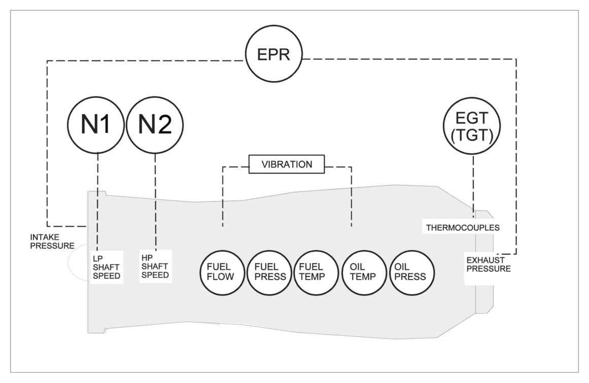
Engine instruments are divided into two fundamental categories:
| Category | Function | Examples |
|---|---|---|
| Performance Indicators | Measure engine thrust/power output | EPR gauge, Fan Speed (N1) gauge, Torque meter |
| Engine Condition Indicators | Monitor engine health/serviceability | EGT gauge, Compressor Speed, Oil Pressure, Oil Temperature |
2. Types of Display
| Type | Description |
|---|---|
| Analogue (Clockwork cockpit) | Multiple individual gauges; conventional needle-and-dial instruments |
| Electronic (Glass cockpit) | CRT or LCD panels with LED digital displays; flexible formatting |
Both types convey essentially the same information, but the glass cockpit offers greater flexibility and is now the preferred means of displaying both flight and engine instrumentation. A small number of conventional gauges are retained in glass cockpit aircraft for backup in case of electronic display failure.
3. Thrust and Power Measuring Instruments
3.1 Jet Pipe Pressure (P7) Gauge
Measures jet pipe (exhaust) pressure directly. Calibrated in inches of mercury (inHg), pounds per square inch (psi), or percentage of maximum thrust.
3.2 Engine Pressure Ratio (EPR) Gauge
Measures the ratio of jet pipe pressure to engine air intake pressure. This is the most common thrust indicator on turbofan engines.
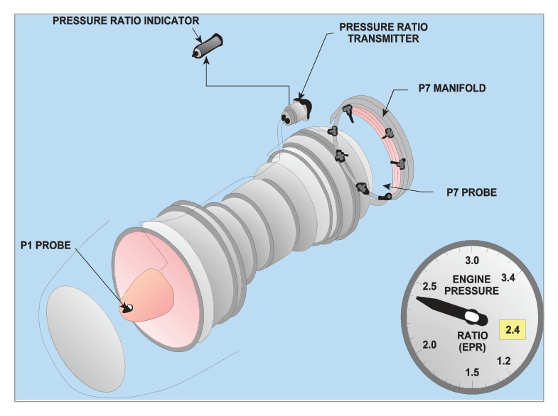
The electronic EPR system uses two transducers that sense the relevant pressures and vibrate at frequencies proportional to those pressures. A computer calculates the electrical signal appropriate to the pressures and sends it to the EPR gauge and to the engine management system.
On some large turbofan engines, an integrated EPR is produced by comparing the integrated turbine discharge pressure and fan outlet pressure against the compressor inlet pressure.
During the take-off roll, as forward airspeed increases, the engine intake pressure rises (ram effect). The jet pipe pressure is initially unaffected at low airspeed. Therefore the EPR ratio (jet pipe ÷ intake) FALLS — this is an apparent drop only, not a loss of thrust.
An inexperienced pilot may attempt to advance throttles further to restore EPR, risking exceedance of N1, N2, N3, and EGT limits.
Standard procedure: EPR must be set before approximately 60 knots — no increase in engine power is permitted after this speed (except in emergency).
After take-off, as airspeed increases beyond V2, the increased intake pressure is transmitted through the engine to the jet pipe, restoring the ratio to the take-off setting.
Worked Example — EPR apparent drop
Assume EPR is set to 1.60 at brake release (intake pressure P₁ = 14.7 psi, jet pipe P₇ = 23.5 psi → EPR = 1.60).
At 60 kt (ram effect): P₁ rises to 15.5 psi; P₇ initially unchanged at 23.5 psi → EPR = 23.5/15.5 = 1.516 (apparent fall).
The engine has NOT lost thrust — the ratio has changed due to the ram rise in intake pressure. Power must NOT be increased at this point.
3.3 Engine Torque (Turboprop/Turboshaft)
Turboprop and turboshaft engines produce torque, not direct jet thrust. Power = Torque × rpm.
Torque is measured between the engine and the reduction gearbox.
| Method | Principle | Key Points |
|---|---|---|
| Oil Torquemeter | Axial thrust on helical gears balanced by engine oil pressure (up to 800 psi) | Oil pressure in cylinders counteracts axial gear load; pressure ∝ torque; bleed hole acts as feedback element |
| Electronic Torquemeter | Phase difference between two concentric shafts (Torque Shaft + Reference Shaft) using exciter wheels and EM pick-ups | AC voltage generated; phase displacement ∝ torque (shaft twist); lighter and more reliable |
Torque indicator units vary by system: psi, inch/foot pounds, newton metres, BHP/SHP, or percentage of maximum. The indicator can show negative torque (windmilling propeller). On FADEC systems, limits can be digitally adjusted.
4. Engine RPM Measurement (Tachometers)
The tachometer (tacho) measures engine rotational speed. For piston engines, it measures crankshaft speed. For gas turbines, it measures compressor speed. There are three basic methods:
4.1 Mechanical (Magnetic) Tachometer
Found on older piston aircraft. Uses a flexible drive shaft connected to a drag-cup indicator:
- A magnet is driven by the engine via the flex drive
- The rotating magnet induces eddy currents in an aluminium/copper drag-cup
- The eddy currents create a torque pulling the drag-cup in the direction of magnet rotation
- A hairspring opposes the motion; the equilibrium position moves the pointer
- Temperature compensation devices are incorporated
4.2 Electrical Generator System (Tacho-Generator)
Possibly the oldest system still in use on large aircraft. Uses a small 3-phase tacho-generator driven by the engine. Output feeds an indicator with an asynchronous motor driving a drag-cup and pointer. Displays percentage of maximum engine speed or actual rpm.
- N1 — Low Pressure compressor spool speed
- N2 — Intermediate Pressure compressor spool speed
- N3 — High Pressure compressor spool speed
N1 and EPR are the primary parameters used to measure thrust in turbojets. The indicator displays percentage speed, with 100% corresponding to optimum turbine speed.
- Fitted concentrically with the main pointer, initially at the maximum rpm graduation
- If the main pointer exceeds the limit, the limit pointer is carried with it and stays at the maximum speed reached
- When speed reduces, the limit pointer remains at the maximum recorded — this is a maintenance record
- Reset: apply a separate 28V DC supply to a solenoid in the indicator
4.3 Inductive Probe (Speed Probe) System
Used where tacho-generators cannot be driven from intermediate or low-pressure shafts. A speed probe is positioned on the compressor casing aligned with a phonic wheel (toothed gear) or actual fan blades.
- As the spool rotates, it alters magnetic flux in the probe
- This changes the current in the probe coil
- The frequency of change is directly proportional to spool speed
- The frequency signal drives the indicator
Advantages: fewer moving parts; can provide multiple outputs (speed indication, engine start warning lamp, automatic power control, flight data acquisition).
4.4 Colour Coding on RPM Indicators
| Colour | Meaning |
|---|---|
| Green | Normal operating range |
| Amber | Caution range |
| Red | Maximum or minimum speed; restricted (vibration) ranges |
4.5 Synchroscope
On multi-engine aircraft, engine speed must be synchronised to reduce structural vibration and noise. The Synchroscope provides a qualitative indication of speed difference between engines:
- One engine is designated master; others are slaves
- Displays whether slave engines are running faster or slower than the master
- Designed to operate from AC generated by the tachometer system
5. Temperature Sensing Equipment
Engine temperature ranges from −56°C to +1200°C. Four types of measuring devices are used:
flowchart LR
    A[Temperature
Measurement] --> B[Expansion Type
e.g. mercury thermometer
bimetallic strip]
    A --> C[Vapour Pressure Type
liquid-to-vapour state change
pressure ∝ temp]
    A --> D[Electrical Type
Resistance bulb RTD
Thermocouple Seebeck Effect]
    A --> E[Radiation Type
Pyrometry
emissivity-based optical]
    B --> F[Low temp
Direct reading]
    C --> F
    D --> G[High temp
Remote sensing]
    E --> G
5.1 Thermocouple (Thermo-electric Type) — Most Important for Turbines
Two dissimilar metals joined at a junction produce a small voltage (thermo-EMF) proportional to the temperature at the junction — the Seebeck Effect.
| Junction | Location | Role |
|---|---|---|
| Hot Junction | In the engine gas stream (the probe) | Senses temperature → generates EMF |
| Cold Junction | Cockpit engine instrument | Reference; EMF measured here on millivoltmeter |
- Chromel (nickel chromium) — positive element
- Alumel (nickel aluminium) — negative element
Selected for: ability to withstand very high temperatures AND a reasonable volts-per-degree ratio. Not the highest milli-voltage output available, but ideal combination of properties.
- The cockpit reads the average temperature of all probes
- If one probe is damaged, the effect on the reading is minimal (slight drop)
- A larger portion of the gas stream is sampled, improving accuracy
5.2 Temperature Probe Locations and Terminology
| Abbreviation | Full Name | Position |
|---|---|---|
| TIT | Turbine Inlet Temperature | Before the turbine |
| TET | Turbine Entry Temperature | Before the turbine |
| TGT | Turbine Gas Temperature | Inside the turbine |
| EGT | Exhaust Gas Temperature | After the turbine |
| JPT | Jet Pipe Temperature | Combined with P7 pitot probes |
Probe position depends on the material's ability to withstand the temperature encountered. TIT/TET locations have the highest temperatures; EGT probes are downstream where temperatures are lower and metal endurance is sufficient.
5.3 Air Temperature — SAT, RAT, TAT
| Term | Definition | Notes |
|---|---|---|
| SAT | Static Air Temperature | True static condition; what performance data requires |
| RAT | Ram Air Temperature | SAT + ram rise (due to adiabatic compression + skin friction at speed) |
| TAT | Total Air Temperature | SAT + full ram rise; probes have ~100% recovery factor; used at high Mach numbers |
6. Pressure Gauges
Pressure = force per unit area. Common units: psi, inHg, bar (1 bar = 14.5 psi), pascal (1 bar = 100,000 Pa). Pressure gauges measure gauge pressure (difference between absolute and atmospheric pressure).
Elastic Pressure Sensing Elements
| Element | Construction | Pressure Range | Application |
|---|---|---|---|
| Diaphragm | Corrugated circular metal disc, secured at edge | Low pressure | General low-pressure sensing |
| Capsule (Aneroid) | Two diaphragms sealed together — sealed chamber (aneroid) or open (pressure capsule) | Low pressure | More sensitive than single diaphragm; altimeters |
| Bellows | Extended corrugated diaphragm principle — accordion-like | High, low, or differential | LP booster pump output |
| Bourdon Tube | C-shaped tube with elliptical cross-section; free end sealed; applied pressure straightens the tube | Higher pressures | Engine oil pressure |
Remote Indicating Pressure Systems
Where it would be impractical to run fluid pipelines to the cockpit (e.g., outer engine of a B747), remote indicating systems are used:
- A transmitter at the pressure source
- An indicator (receiver) on the cockpit panel
- Can be AC or DC operated
- Advantage: hazardous fluids (e.g., engine oil, hydraulic fluid) need not be piped into the cockpit
- Saves weight by reducing pipeline length
7. Engine Vibration Monitoring
Vibration Monitoring Equipment (VME) is fitted to almost all commercial jet aircraft. Gas turbines have very low inherent vibration; any increase is indicative of damage that may lead to failure.
Sensor Types
| Sensor | Principle |
|---|---|
| Piezoelectric crystal | Crystal generates electrical charge when mechanically stressed by vibration |
| Moving coil / magnet | Loosely mounted magnet moves within a fixed coil; relative motion generates a signal |
VME Operation
Both sensor types are suspended within a fixed coil carrying 115 volts at 400 Hz. The sensor moves in sympathy with engine vibration. The signal is:
- Filtered: only frequencies indicative of damage pass through (normal engine frequencies are erased)
- Amplified by the amplifier
- Rectified and sent to the vibration indicator
Vibration is measured and displayed in Relative Amplitude (Rel Ampl). If vibration exceeds a predetermined threshold, a warning light illuminates on the instrument.
8. Fuel Quantity and Flow Measurement
8.1 Volume vs. Mass Measurement
| Method | Units | Application | Limitation |
|---|---|---|---|
| Volume measurement | Gallons/litres | Light aircraft only | Does not account for density changes with temperature |
| Mass measurement | kg or lb | All commercial aircraft | More complex system required |
8.2 Float System (DC Volume)
A float rests on the fuel surface. Its movement repositions a wiper on a variable resistor, altering current to a cockpit indicator. Simple but has two significant errors:
- Fuel tanks are rarely symmetrical — float level is not a true measure of quantity
- Errors occur during manoeuvres as attitude changes affect float position
The gauge is set to be accurate only at the low and empty positions.
8.3 Capacitance Fuel Gauge System
The standard system on commercial aircraft. Measures mass using the relationship between fuel level (dielectric permittivity) and capacitance.
C = Er × (A / D)
Where:
- C = Capacitance (farads; typically picofarads, 10⁻¹² F)
- Er = Relative Permittivity of the dielectric (fuel or air)
- A = Area of plates (constant)
- D = Distance between plates (constant)
Since A and D are fixed, capacitance varies only with Er — which changes as the ratio of fuel to air in the tank changes.
Typical Dielectric Values
| Material | Relative Permittivity (Er) |
|---|---|
| Vacuum / Air | 1.0 / 1.0006 |
| Gasolene | 1.95 |
| Kerosene | 2.10 |
| Distilled Water | 81.00 |
| Impure Water | 0 (effectively shorts capacitor) |
Reference Unit and Temperature Compensation
- A Reference Unit is always submerged in the unusable fuel to improve accuracy when permittivity changes from normal
- A Compensating Capacitor corrects for temperature-induced changes in fuel density and Er, allowing the system to indicate mass rather than volume
- The system senses changes in Specific Gravity (SG) to indicate mass
Fail-Safe and Test Features
- On failure: indicator slowly drives to zero (fail-safe)
- A test circuit simulates tank emptying; on release, pointer returns to original position
- A Fuel Totalizer can display the sum of all tank gauges
8.4 Fuel Flowmeter
Measures instantaneous fuel consumption rate. Units: volume flow (gallons/hr or litres/hr) or mass flow (lb/hr or kg/hr).
Modern flowmeter uses an electrical sensor with a helical vane impeller containing an embedded magnet. Fuel flow rotates the impeller → pick-off coil generates a sinusoidal signal at frequency proportional to volume flow rate. Temperature correction converts this to mass flow.
The flowmeter is located in the high-pressure fuel line to the burners. An Integrated Flowmeter displays both fuel flow rate and total fuel consumed (rate integrated over time).
9. Remote Signal Transmission & Flight Hour Meter
Remote indicating systems are used to indicate the position of valves, flaps, or levers on engines to the cockpit. Each system comprises:
- A Transmitter at the source position to be measured
- A Receiver (indicator) on the appropriate cockpit panel
- Can be AC or DC operated
Flight Hour Meter
Records engine and systems usage time. Activated automatically via the weight-on-wheels switch or (more commonly) an airspeed switch.
- Performance indicators: EPR, N1, Torque. Condition indicators: EGT, N2, oil pressure/temp.
- EPR apparent drop during take-off at low speed — set EPR before 60 kt, no increase after.
- Torquemeter: oil pressure type (up to 800 psi) or electronic phase-shift type. Measured between engine and reduction gearbox.
- Tacho methods: Mechanical (eddy current drag-cup), Generator (3-phase), Inductive probe (phonic wheel). N1=LP, N2=IP, N3=HP.
- Thermocouple: Chromel/Alumel. Hot junction in gas stream, cold junction at cockpit. Parallel probes → average reading. No external power for indication.
- Temperature: SAT → RAT → TAT (TAT = SAT + full ram rise, ~100% recovery factor).
- Pressure elements: Diaphragm/Capsule (low), Bellows (variable), Bourdon tube (high/oil pressure).
- VME: Piezo or magnet/coil sensor. Filter → amplifier → rectifier → display in Rel Ampl.
- Capacitance fuel gauge: C = Er × A/D. Water → reads beyond full scale. Reference unit always submerged. Fail-safe = drives to zero.
Practice Questions & Detailed Answers
- (a) — EGT and N2 are Engine Condition Indicators (health monitoring), not performance/thrust indicators.
- (b) — Oil pressure and temperature are Condition Indicators.
- (d) — Vibration level and fuel flow are condition/monitoring parameters, not primary thrust indicators.
- (a) — Advancing throttles would risk exceeding N1/EGT limits without genuine benefit; the EPR drop is NOT a real thrust loss.
- (c) — This is normal and expected behaviour; it is not a malfunction.
- (d) — Atmospheric pressure does not change significantly during a take-off roll.
- (a) — The thermocouple probe is self-generating; it does not receive power.
- (c) — 115V/400Hz is associated with VME (vibration monitoring), not thermocouple indicating.
- (d) — 28V DC is associated with the overspeed pointer reset solenoid in tachometers, not thermocouple systems.
- (a) — Zero indication is the system's fail-safe response to a fault, not a water response.
- (b) — The system cannot compensate for water; the reference unit only compensates for fuel permittivity/temperature variation.
- (d) — Random fluctuation is not the described failure mode; water causes a consistent over-reading.
- (a) — Aneroid capsule is a sealed (evacuated) capsule used to measure low pressures (e.g., altitude).
- (b) — Corrugated diaphragm is used for low pressures.
- (c) — Bellows can measure high, low, or differential pressures, but are specifically cited for LP booster pump output — not the primary high-pressure element.
- (a) — Ram rise is positive (adds to SAT), not subtracted.
- (b) — Above Mach 0.2, friction and adiabatic compression raise air temperature above SAT.
- (d) — 80% recovery factor applies to a specific sensor type, not to TAT by definition. TAT by definition has ~100% recovery.
Master Reference Tables
Numerical Values — Quick Reference
| Parameter | Value | Section |
|---|---|---|
| P7 gauge calibration units | inHg, psi, or % max thrust | 3 |
| EPR set before this speed on take-off | 60 knots | 3 |
| Oil torquemeter max pressure | 800 psi | 3 |
| Gas turbine speed display | 100% = optimum turbine speed | 4 |
| Overspeed pointer reset supply | 28V DC | 4 |
| VME coil supply voltage/freq | 115V / 400Hz | 7 |
| Engine temp range monitored | −56°C to +1200°C | 5 |
| TAT recovery factor | ~100% | 5 |
| Er — Air | 1.0006 | 8 |
| Er — Kerosene | 2.10 | 8 |
| Er — Gasolene | 1.95 | 8 |
| Er — Distilled water | 81.00 | 8 |
| Red arc on fuel gauge required if unusable fuel exceeds | 1 gallon or 5% of tank capacity | 8 |
| 1 bar = | 14.5 psi = 100,000 Pa | 6 |
Answer Key
| Q | Ans | Topic |
|---|---|---|
| 1 | c | Performance vs Condition indicators |
| 2 | b | EPR apparent drop during T/O |
| 3 | b | Thermocouple power supply |
| 4 | c | Water contamination — capacitance gauge |
| 5 | d | Bourdon tube — high pressure |
| 6 | c | TAT = SAT + ram rise |
Reinforce Chapter 38: Engine Instrumentation
Test your knowledge and practice actual exam questions for Navigation — Instrumentation.