Electronic Instrumentation
by Ghost Aviator
Table of Contents
- Introduction — EICAS and ECAM
- EICAS — System Overview
- EICAS — Display Units and Colour Coding
- EICAS — Display Modes
- EICAS — Display Select Panel
- EICAS — Alert Messages
- EICAS — Display Unit Failure
- EICAS — Standby Engine Indicator
- ECAM — System Overview and Display Units
- ECAM — Display Modes
- ECAM — Control Panel
- Practice Questions & Detailed Answers
- Master Reference Tables
1. Introduction — EICAS and ECAM
The display of engine performance and airframe systems parameters via CRT or LCD display has become standard on modern aircraft. Two principal systems are in use:
| System | Full Name | First Aircraft | Manufacturer |
|---|---|---|---|
| EICAS | Engine Indicating and Crew Alerting System | Boeing 757 and 767 | Boeing |
| ECAM | Electronic Centralized Aircraft Monitoring | Airbus A310 | Airbus |
| Aspect | EICAS | ECAM |
|---|---|---|
| Engine data display | Always displayed on screens; eliminates traditional instruments | Originally displayed on conventional instruments (A310); A320 onward: ECAM displays engine data |
| System display format | Alphanumeric messages and digital/analogue data | Check-list and schematic/synoptic format |
| Traditional instruments | Eliminated (small standby set retained) | Retained in A310; eliminated in later Airbus types |
2. EICAS — System Overview
The basic EICAS system comprises:
- Two display units (upper and lower)
- One control panel
- Two computers — designated 'Left' and 'Right'
Only one computer is in control at a time; the other is on standby. In the event of computer failure, the standby can be selected either manually or automatically.
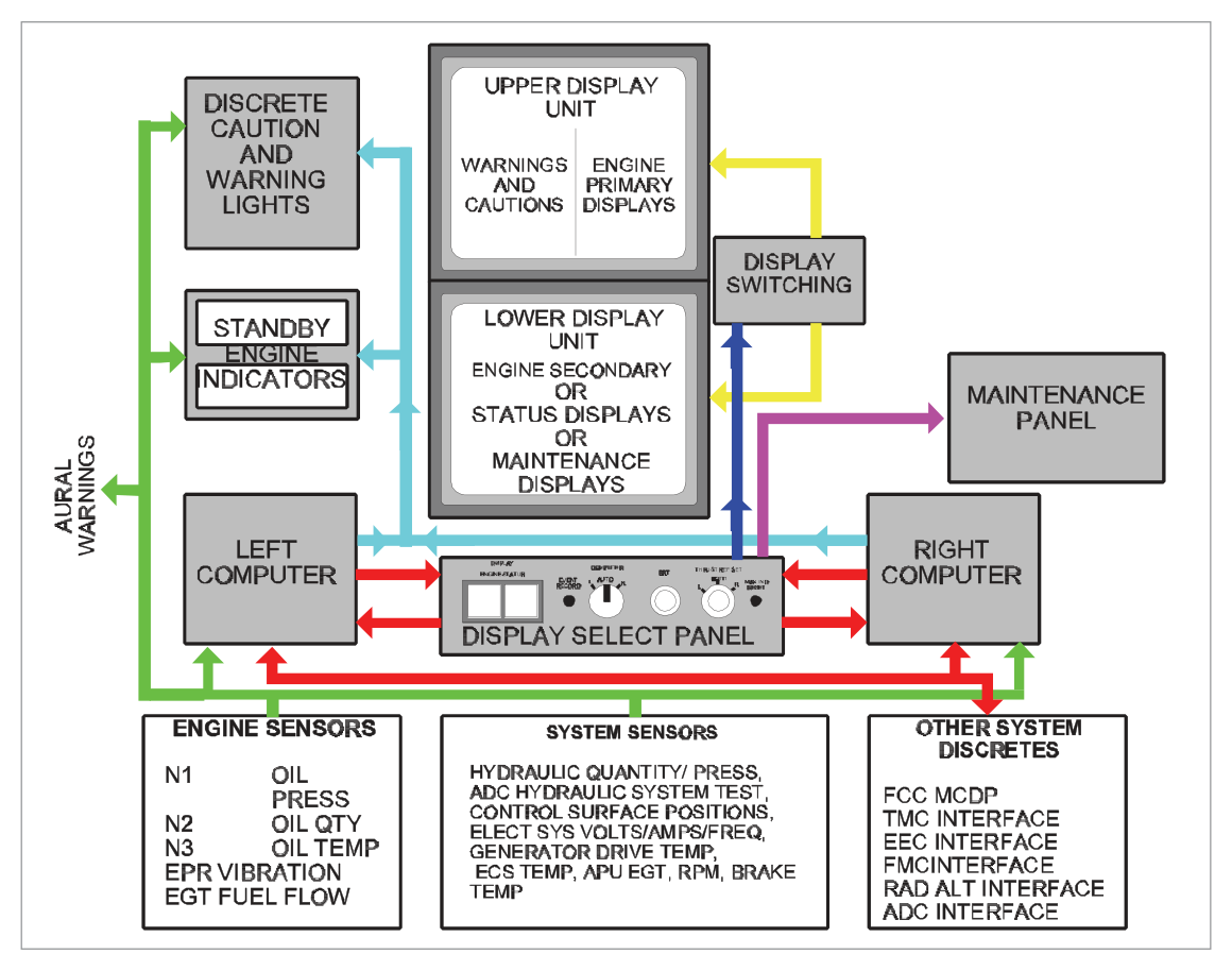
- Primary engine parameters — displayed full-time
- Secondary engine parameters — displayed as required
- Warning, caution, and advisory alert messages — displayed as required
3. EICAS — Display Units and Colour Coding
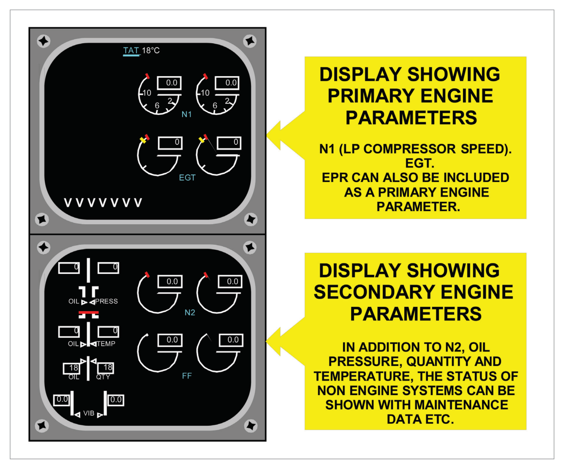
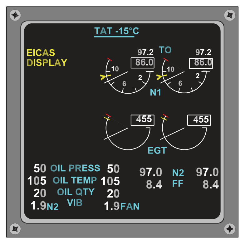
The two display units are mounted one above the other and use colour shadow mask CRTs (or LCD equivalents):
| Display Unit | Normal Content |
|---|---|
| Upper Display Unit | Primary engine parameters: N1 speed, EGT, and warning/caution messages. May also show EPR depending on engine type and thrust management system. Shows rows of 'V's when secondary info is on lower unit. |
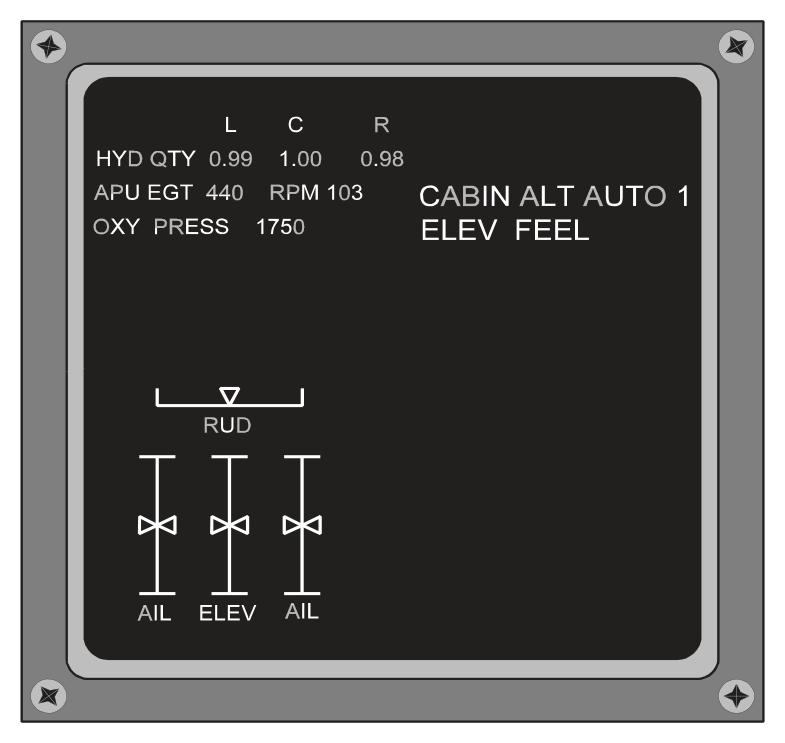
| Lower Display Unit | Secondary engine parameters: N2 speed, fuel flow, oil quantity/pressure/temperature, engine vibration. Also: non-engine system status (flight control surface positions, hydraulic, APU, etc.), aircraft configuration, maintenance data. Normally blank in flight. |
EICAS Colour Coding (Seven Colours)
| Colour | Use |
|---|---|
| White | All scales, normal operating range of pointers, digital read-outs |
| Red | Warning messages, maximum operating limit marks, digital read-outs at max limits |
| Green | Thrust mode read-out; selected EPR/N1 target cursors |
| Blue | System testing only |
| Yellow/Amber | Caution and advisory messages; caution limit marks; digital read-outs at caution limits |
| Magenta | In-flight engine starting; cross-bleed messages |
| Cyan | Names of all parameters being measured (e.g., N1, oil pressure, TAT); status marks/cues |
- Red = Warnings, max limits (immediate action required)
- Amber/Yellow = Cautions and advisories (crew awareness)
- Green = Target/selected thrust references
- White = Scales and normal readouts
- Cyan = Parameter names/labels
- Magenta = In-flight engine start / cross-bleed
- Blue = Test mode only
4. EICAS — Display Modes
EICAS has three modes:
flowchart LR
    A[EICAS Display Modes] --> B[Operational Mode
Selected by flight crew
In-flight engine data + alerts]
    A --> C[Status Mode
Selected by flight crew
Dispatch readiness / MEL check]
    A --> D[Maintenance Mode
Selected on maintenance panel
Ground use only — 5 formats]
    B --> E[Upper DU active
Lower DU blank unless
selected]
    C --> F[Lower DU shows:
control surface positions
sub-system data
equipment status messages]
    D --> G[Lower DU only
NOT available in flight]
| Mode | Selected By | Purpose | Display Unit |
|---|---|---|---|
| Operational | Flight crew (Display Select Panel) | In-flight engine operating information and alerts requiring crew action | Upper DU (continuously); Lower DU on request |
| Status | Flight crew (Display Select Panel) | Dispatch readiness; associated with MEL; flight control surface positions; selected sub-system parameters; equipment status messages | Lower DU |
| Maintenance | Maintenance panel (ground engineers only) | Trouble-shooting and verification testing in 5 display formats | Lower DU — NOT available in flight |
5. EICAS — Display Select Panel
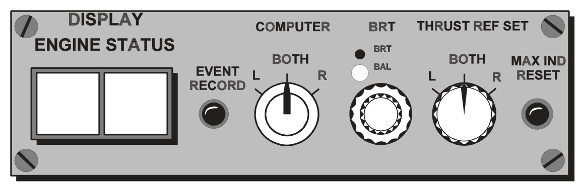
Located on the centre pedestal. Usable both in flight and on the ground. Controls include:
| Control | Type | Function |
|---|---|---|
| Engine Display Switch | Momentary push | Removes or presents secondary information on the lower DU |
| Status Display Switch | Momentary push | Displays Status Mode (status page) on lower DU |
| Event Record Switch | Momentary push | Records fault data: automatically (auto event) for malfunctions, or manually (manual event) by crew. Data stored in non-volatile memory; retrievable only on ground via maintenance panel. |
| Computer Select Switch | Rotary | AUTO = selects left (primary) computer and auto-switches on failure; Manual = left or right selection |
| Display Brightness Control | Dual knob | Inner = display intensity; Outer = brightness balance between displays |
| Thrust Reference Set Switch | Pull & rotate inner; outer selects engine | Positions reference cursor on EPR or N1 thrust indicator for selected engine |
| Maximum Indicator Reset Switch | Pushbutton | Clears exceeded-parameter alerts from display when the excess condition no longer exists |
6. EICAS — Alert Messages
EICAS continuously monitors over 400 inputs from engine and airframe sensors. Faults generate messages displayed on the upper DU in urgency order. Up to 11 messages can be displayed simultaneously.
| Level | Colour | Name | Action Required | Additional Alerts |
|---|---|---|---|---|
| Level A | RED | Warning | Immediate corrective action | Master Warning lights illuminated; aural warning (e.g., fire bell) from central warning system |
| Level B | AMBER | Caution | Immediate crew awareness + future crew action | Message caution lights; aural tone repeated twice |
| Level C | AMBER (indented) | Advisory | Crew awareness only | No caution lights or aural tones |
Message Management
| Action | Effect |
|---|---|
| CANCEL switch | Removes only caution and advisory messages; Warning messages cannot be cancelled |
| RECALL switch | Brings back cancelled caution/advisory messages; word 'RECALL' appears at bottom of display |
| Message auto-removal | When associated condition no longer exists, message automatically removed; lower messages move up |
| New fault insertion | New message inserted at appropriate line; older messages move down one line |
| More than 11 messages | Excess messages form a 'page'; lowest message replaced by page number (white, lower right). Press CANCEL to see next page; warnings carried over. |
7. EICAS — Display Unit Failure
If the lower display unit fails while secondary information is displayed:
- An amber alert message appears at the top left of the upper DU
- Secondary information is transferred to the upper DU in 'compact' format
- The compact format can be removed by pressing the 'ENGINE' switch on the display select panel
- The STATUS switch is inhibited — the status page cannot be displayed while the lower DU has failed
8. EICAS — Standby Engine Indicator
The Standby Engine Indicator provides primary engine information in the event of a total loss of EICAS displays. It displays:
- N1 speed
- N2 speed
- EGT
Displayed using LCD type indicators. Operating limit values are also shown.
9. ECAM — System Overview and Display Units
The ECAM system as originally developed for the Airbus A310 processes and displays data primarily related to primary systems of the aircraft in check-list and synoptic/pictorial format. Engine data was displayed by conventional instruments in the A310; the A320 onward integrates engine data into ECAM.
Display Unit Layout and Roles
| Display Unit | Location | Content |
|---|---|---|
| Left-hand DU | Side-by-side | Status of systems, warnings, corrective action — in sequenced check-list format |
| Right-hand DU | Side-by-side | Associated information in pictorial or synoptic (schematic) format |
- EICAS: Displays mounted one above the other (upper and lower)
- ECAM: Displays mounted side by side (left and right) — though some installations differ
10. ECAM — Display Modes
ECAM has four display modes — three automatic and one manual:
flowchart TD
    A[ECAM Display Modes] --> B[1. Flight Phase-related
AUTOMATIC
Normal operations]
    A --> C[2. Advisory — Mode and Status
AUTOMATIC
Status summaries]
    A --> D[3. Failure-related
AUTOMATIC — highest priority
Takes precedence over all other modes]
    A --> E[4. Aircraft System Display
MANUAL
Crew-selected via illuminated push-buttons]
    D --> F[Left DU: corrective action
Right DU: system diagram
+ Aural warning + Warning light]
    E --> G[Selects any of 12 systems
for routine checking]
Mode 1 — Flight Phase-related
Automatically selects displays appropriate to the current phase of aircraft operation: preflight, take-off, climb, cruise, descent, approach, after landing.
- Left DU: Advisory memo mode
- Right DU: Aircraft diagram (fuselage, doors, escape slide arming status, etc.)
Mode 2 — Advisory (Status)
Status messages displayed on the left DU provide the flight crew with:
- Operational summary of aircraft condition
- Possible downgrading of autoland capability
- Aircraft status after failures (where not flight-affecting)
Mode 3 — Failure-related (Highest Priority)
Takes precedence over all other automatic modes AND the manual mode. When a failure occurs:
- Right DU: immediately displays a diagram of the affected system
- Left DU: displays corrective action for the crew
- Additional: aural warning sounded; warning light on central warning panel illuminated
- As corrective action is taken, left DU instructions are replaced by a white confirmation message
- The right DU diagram is 'redrawn' to reflect the new configuration
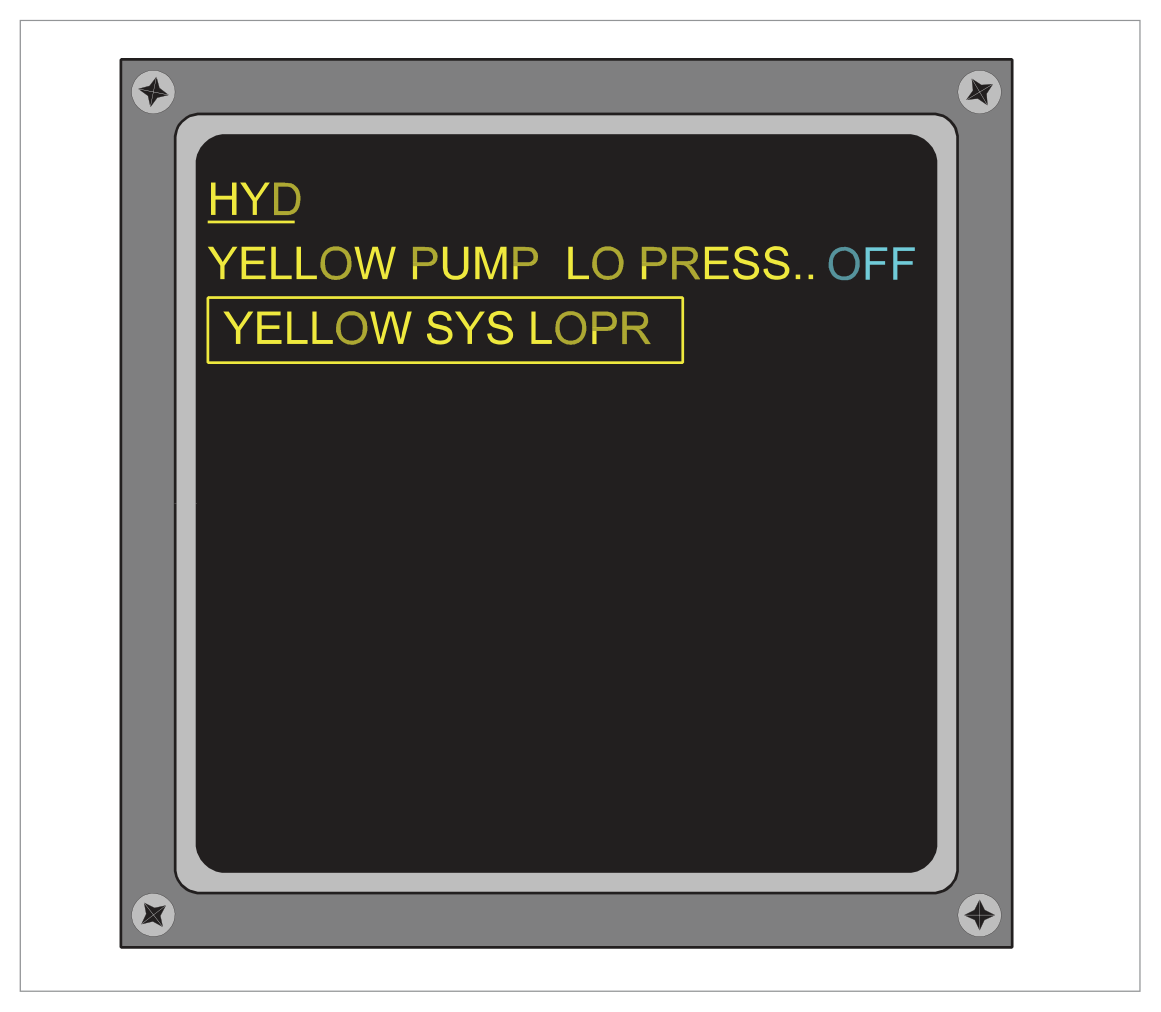
- Single system failure: system title is underlined
- Failure affecting other sub-systems: system title is shown boxed
Warnings and lights are cleared using 'CLEAR' (CLR) push-button switches on the ECAM control panel or warning light display panel.
Mode 4 — Aircraft System Display (Manual)
Permits selection of diagrams related to any one of 12 aircraft systems for routine checking. Also permits selection of status messages when no warnings are active. Selected via illuminated push-button switches on the ECAM system control panel.
11. ECAM — Control Panel
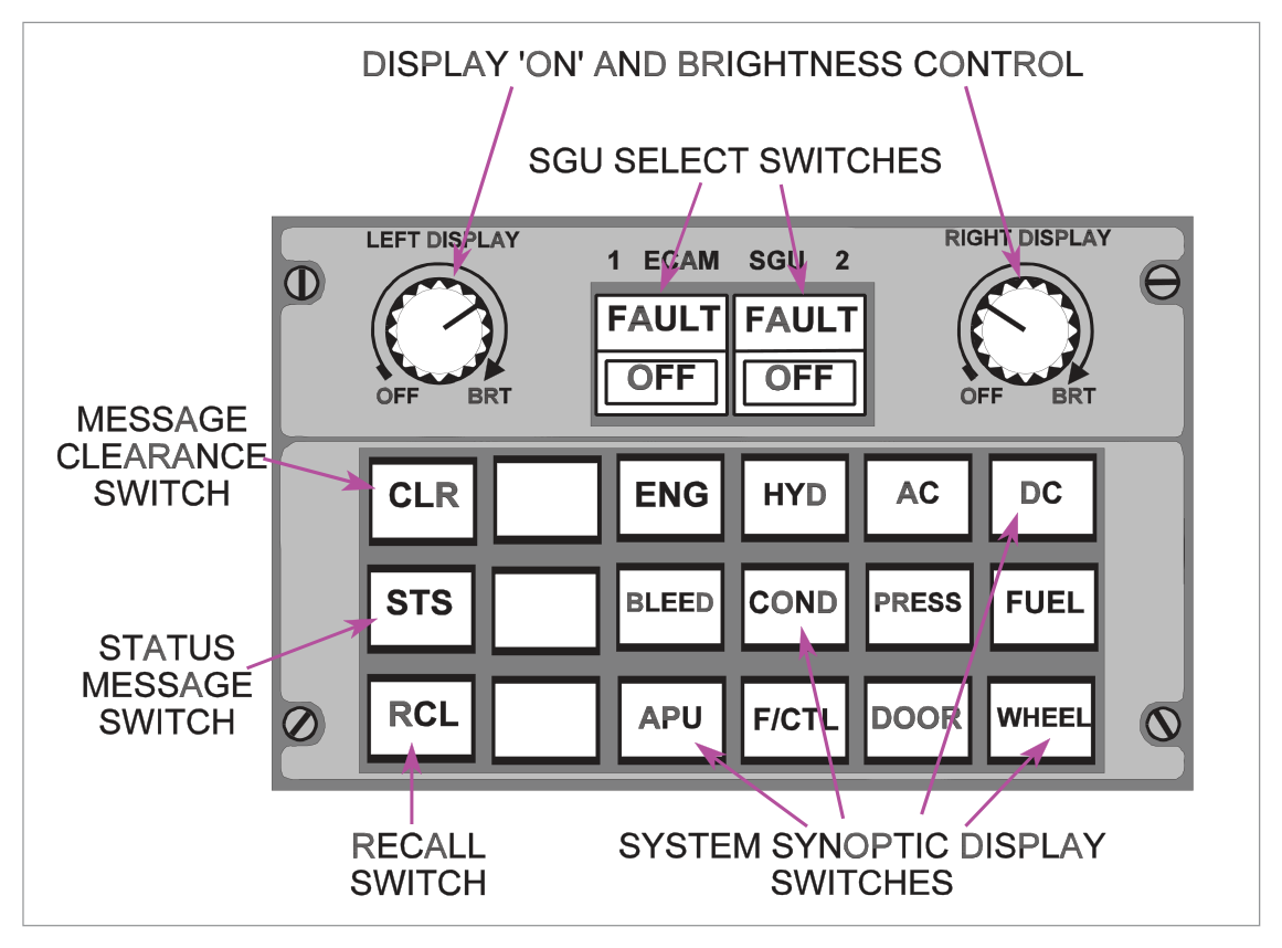
| Switch | Function |
|---|---|
| SGU Selector Switches | Control respective Symbol Generator Units (SGUs). Lights off in normal operation. FAULT caption (amber) = SGU internal self-test failure. Releasing switch: isolates SGU, FAULT extinguishes, OFF caption illuminates white. |
| Synoptic Display Switches | Individually select synoptic diagrams for each of 12 systems; illuminate white when pressed. Automatically cancelled when a warning or advisory occurs. |
| CLR (Clear) Switch | Illuminates white when a warning or status message is on left DU. Press to clear messages. |
| STS (Status) Switch | Manual selection of aircraft status message (only when no warning displayed); illuminated white. Also causes CLR to illuminate. Suppressed if warning occurs or CLR is pressed. |
| RCL (Recall) Switch | Recalls previously cleared warning messages IF the failure condition still exists. Causes CLR to illuminate. If failure no longer exists: 'NO WARNING PRESENT' displayed on left DU. |
- EICAS: Boeing. Two DUs (upper/lower). 3 modes (Operational, Status, Maintenance). 3 alert levels (A=Red/Warning, B=Amber/Caution, C=Amber-indented/Advisory). Monitors >400 inputs. Up to 11 messages. Standby: N1/N2/EGT on LCD.
- ECAM: Airbus. Two DUs (left/right — side by side). 4 modes (3 automatic + 1 manual). Left DU = checklist/corrective action. Right DU = synoptic/diagram. Failure-related = highest priority. 12 systems in manual mode.
- Key EICAS colours: Red=Warnings; Amber=Cautions+Advisories; Green=Thrust targets; Cyan=Labels; Magenta=Eng start/cross-bleed; Blue=Test.
- EICAS Lower DU failure: Compact format on upper DU; STATUS switch inhibited.
- ECAM failure display: Underlined = single system; Boxed = affects sub-systems.
Practice Questions & Detailed Answers
- (a) — The secondary (lower) DU shows secondary parameters (N2, fuel flow, oil, vibration), NOT primary instruments continuously.
- (b) — N2, N3 and oil pressure are secondary parameters shown on the lower DU; they are not the primary display content.
- (d) — Primary instruments (N1, EGT, EPR) are on the upper DU only in Operational Mode — not on both DUs simultaneously.
- (b) — Flight Phase-related is one of the three automatic modes; it is not an alternative "fourth mode."
- (c) — EICAS has only 3 modes (Operational, Status, Maintenance); there is no fourth EICAS mode.
- (d) — No such cross-over mode exists.
- (a) — Partially correct on the mode names but wrong about which are automatic — status and maintenance are NOT automatic (both require selection); operational is the normal/default mode.
- (b) — Flight phase related, advisory and failure related are ECAM automatic modes, not EICAS modes.
- (d) — Flight phase related is an ECAM mode; not an EICAS mode.
- (b) — EICAS has no "central display unit"; it has upper and lower DUs.
- (c) — The compact format only appears on the EICAS upper DU, not on the EFIS displays.
- (d) — The compact format appears automatically (not when STATUS is pressed); in fact, STATUS is inhibited following lower DU failure.
- (a) — ECAM does not have two control panels with port-only control on failure; this description is inaccurate.
- (c) — While the standard ECAM layout is side-by-side, saying "only" is incorrect — some compact installations differ.
- (d) — This is exactly backwards: the LEFT DU shows corrective action (checklist); the RIGHT DU shows the synoptic/diagram.
- (a) — Level C is advisory (awareness), NOT warning (immediate action). Level A = warning.
- (b) — Level A is a WARNING requiring immediate corrective action — not a caution.
- (c) — Level B is a CAUTION (immediate awareness + future action) — not an advisory. Level C = advisory.
- (a) — There is no ECAM mode changeover on an EICAS aircraft; they are separate, non-interchangeable systems.
- (b) — Both EICAS and ECAM use 2 display units; EICAS does not use 3.
- (d) — Neither EICAS nor ECAM is described as having an emergency interconnect to EFIS symbol generators.
- (a) — "Always automatically" is too absolute; the right DU schematic is related to the specific system/failure being displayed, not continuously shown.
- (c) — Reversed: left = checklist, right = synoptic (NOT left = synoptic, right = corrective action).
- (d) — Continuous primary engine display is an EICAS feature (upper DU); ECAM did not originally display engine data (A310 used conventional gauges).
- (a) — "Electronic Management and Control Section" is not a real avionics system acronym.
- (b) — "Electronic Indication and Fail Safe system" does not exist.
- (c) — EICAS (Engine Indicating and Crew Alerting System) has only 3 modes total, not 3+1.
- (a) — Boxed format is an ECAM convention, not EICAS.
- (b) — A fault NOT affecting other systems is shown underlined, not boxed.
- (c) — Incorrect on both counts: boxed = affects sub-systems AND it's ECAM (not EIAS).
- (b) — Secondary DU shows secondary parameters; fire warning (Level A) goes to the upper DU in red, not amber on the lower DU.
- (c) — EFIS does not display EICAS engine fire alerts; these systems are separate.
- (d) — The FMC primary panel is not an alert display for engine fire warnings.
- (a) — N2 is a secondary parameter; EPR+EGT+N1 are primary. Including N2 in primary instruments is incorrect.
- (b) — ECAM originally showed engine data on conventional (non-electronic) instruments in A310; the ECAM lower/right DU shows synoptic information, not primary engine instruments.
- (d) — In ECAM, the left DU shows warnings/checklist; engine primary instruments are not on an ECAM screen as described. This is EICAS architecture, not ECAM.
Master Reference Tables
EICAS vs ECAM — Master Comparison
| Parameter | EICAS | ECAM |
|---|---|---|
| Manufacturer | Boeing | Airbus |
| First aircraft | B757/B767 | A310 |
| DU layout | Upper / Lower (stacked) | Left / Right (side by side) |
| Number of modes | 3 | 4 (3 auto + 1 manual) |
| Mode names | Operational, Status, Maintenance | Flight Phase-related, Advisory, Failure-related, Manual (Aircraft System Display) |
| Highest priority mode | Operational | Failure-related |
| Maintenance mode availability | Ground only | N/A (no separate maintenance mode) |
| Inputs monitored | >400 | — |
| Max messages displayed | 11 | — |
| Backup for total display loss | Standby engine indicator (N1/N2/EGT, LCD) | — |
| Single system fault display | Red/Amber message | Underlined title |
| Multi-system fault display | Red/Amber message | Boxed title |
| Level A/Warning | RED — Immediate action + Master Warning + aural | — |
| Level B/Caution | AMBER — Awareness + aural tone ×2 | — |
| Level C/Advisory | AMBER (indented) — Awareness only | — |
| Advisory differentiation | Indented one space right | — |
| Warning cancellation | Cannot be cancelled | CLR button |
| Number of manual systems (ECAM) | — | 12 |
Answer Key — Source Questions
| Q | Ans | Topic |
|---|---|---|
| 1 | c | EICAS upper DU content |
| 2 | a | ECAM — 3 auto + 1 manual modes |
| 3 | c | EICAS 3 modes |
| 4 | a | EICAS lower DU failure |
| 5 | b | ECAM left DU = checklist |
| 6 | d | Alert messages — top left of upper DU |
| 7 | c | EICAS or ECAM — not both |
| 8 | b | ECAM left=checklist, right=synoptic |
| 9 | d | ECAM = 3 auto + 1 manual |
| 10 | d | Boxed = sub-system affected = ECAM |
| 11 | a | Fire = red on primary/upper DU |
| 12 | c | EICAS normal ops = upper DU only |
Reinforce Chapter 39: Electronic Instrumentation
Test your knowledge and practice actual exam questions for Navigation — Instrumentation.