The Turn and Slip Indicator
by Ghost Aviator
Table of Contents
- Overview of the Instrument
- The Rate Gyro — Principle
- Operation — Spring and Precession Equilibrium
- Constructional Details and Calibration
- Effect of Varying Rotor Speed
- Errors in the Looping Plane
- The Slip Indicator
- Operating Principles of the Slip Indicator
- Turn and Slip Displays
- Rate 1 Turn Calculations
- Practice Questions & Detailed Answers
- Master Reference Tables
1. Overview of the Instrument
The Turn and Slip Indicator (also called Turn and Bank Indicator or TBI) incorporates two measuring devices, both indicating on the same instrument face:
- Rate of Turn Indicator — uses a rate gyro to measure rate of turn about the vertical axis.
- Slip Indicator — a simple pendulous device (ball in a curved tube) showing whether the turn is balanced (correct bank for TAS and rate of turn), or indicating slip or skid.
2. The Rate Gyro — Principle
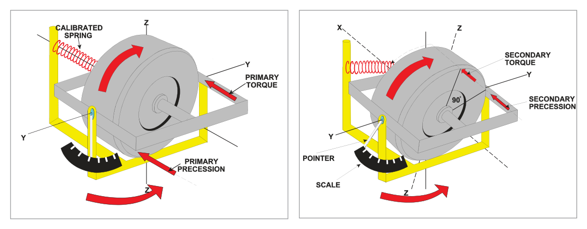
The turn indicator is based on a horizontal-axis rate gyro with only one gimbal and therefore only one degree of freedom.
- If the aircraft banks (without turning) — the gyro axis has the freedom to remain horizontal (no effect).
- If the aircraft yaws (turns) — the frame (fixed to the airframe) applies a force (primary torque) about the ZZ axis, where the gyro has no freedom. This causes a primary precession about the YY axis, tilting the gyro.
A spring system prevents the gyro from turning all the way to the vertical. The amount of spring stretch is a measure of the rate of turn.
3. Operation — Spring and Precession Equilibrium
When the aircraft turns:
- Primary torque acts about the ZZ axis (the aircraft yaws).
- Primary precession occurs about the YY axis → the gimbal tilts.
- As the rotor tilts, the spring between gimbal and frame extends.
- Spring tension applies a secondary torque about the YY axis.
- This secondary torque, with precession, continues until gimbal tilt gives spring tension producing a rate of secondary precession equal to the rate of turn → equilibrium.
The chain of events is virtually instantaneous — as the aircraft goes into a turn, the gimbal immediately takes up the appropriate angle of tilt. If the rate of turn changes, the tilt changes to re-establish the balance. The angle of tilt is thus a measure of the rate of turn.
- First graduation = Rate 1 turn = 3°/second (360° in 2 minutes).
- Second graduation = Rate 2 = 6°/second.
- Higher rates are possible depending on instrument.
4. Constructional Details and Calibration
Suction and electrically-driven types are available. For suction types, an engine-driven pump or venturi applies suction; replacement air enters via a filter and is directed as a jet at buckets on the rotor periphery.
Rotor rpm are low compared with the DGI and AH (because precession is used, not rigidity).
A damping system (piston-in-cylinder or electromagnetic device) reduces oscillation of the gimbal.
Stops limit gimbal movement to a tilt corresponding to a turn of about 20°/second. Because there is only one gimbal, the gyro will not topple when it comes against the stops.
TAS Calibration and Error
Calibration of correct rate of turn (spring tension) is optimized for a design TAS. However, only a small error is introduced even for quite large departures from design TAS. One manufacturer quotes:
| Specification | Value |
|---|---|
| Maximum TAS error over operating range | 5% |
| TAS range quoted | 85 to 350 knots |
| Design calibration TAS | 260 knots |
5. Effect of Varying Rotor Speed
| Condition | Rotor State | Rigidity | Indication |
|---|---|---|---|
| Inadequate suction (high altitude, choked filter, leaking tube) | Underspeeding | Lowered | Under-reads rate of turn |
| Excessive suction | Overspeeding | Increased | Over-reads rate of turn |
6. Errors in the Looping Plane
In a gently banked turn, the aircraft turns mainly in the yawing plane. In a steep turn there is more movement in the looping plane. Normally this means rotation about the rotor axis with no effect. However, if the gimbal is already tilted (from a preceding yaw), movement in the looping plane causes additional precession of the rotor.
In a steep turn, the usual positive movement in the looping plane will increase the gimbal tilt — causing the indicator to over-read, sometimes coming against the stops.
7. The Slip Indicator
The slip indicator indicates whether a turn is properly balanced (correct bank angle for TAS and rate of turn), or whether the aircraft is slipping in or skidding out.
Rule of Thumb for Rate 1 Bank Angle
Valid for Rate 1 turns with TAS between 100 and 250 knots.
Example: TAS 150 kt → Bank = 15 + 7 = 22°
Construction
The modern slip indicator is a 'ball-in-tube inclinometer' — a solid ball in a curved tube containing liquid that damps out oscillations. Early types used a simple metal pendulum with piston-in-cylinder damping. The heavy ball behaves like a pendulum, with the centre of curvature of the tube acting as the effective suspension point.
8. Operating Principles of the Slip Indicator
Level Flight
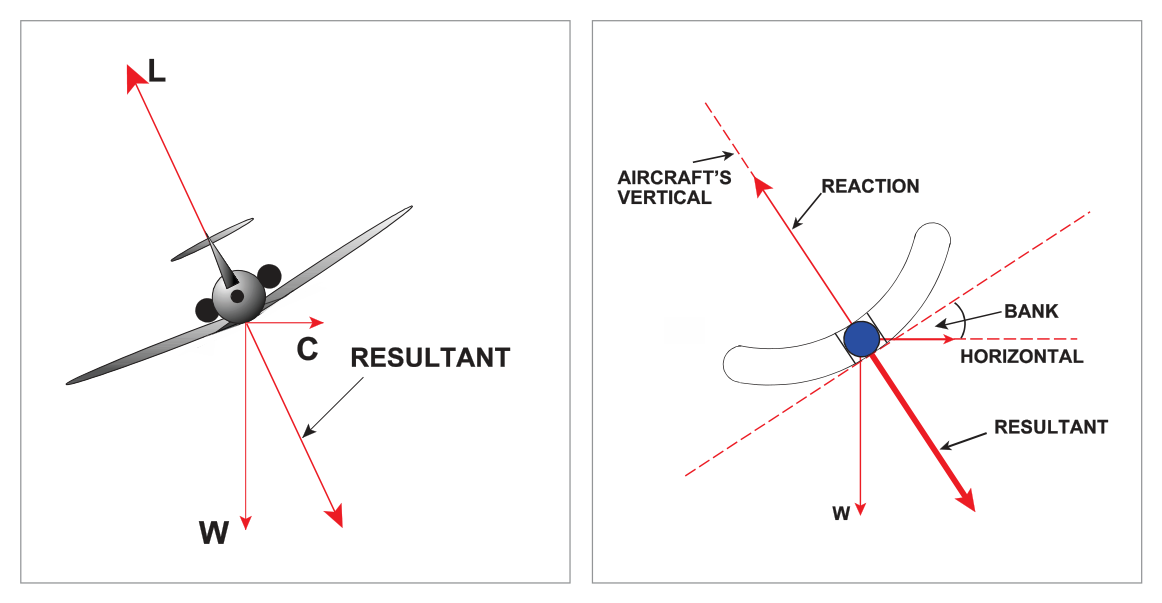
Weight W of the ball acts downwards; equal and opposite reaction from the base of the tube acts upwards towards the centre of curvature. Wings level → ball lies between the two etched lines.
Balanced Turn
In a balanced turn, the ball rolls outward due to centrifugal force, taking up a new equilibrium where the reaction of the tube base balances the resultant of ball weight and centrifugal force. Because both aircraft and ball experience the same TAS and rate of turn (same centripetal acceleration), their resultant force vectors are parallel. When the ball is central, the turn is balanced — lift equals the resultant of weight and centrifugal force.
Unbalanced Turns
| Ball Position | Turn State | Correction |
|---|---|---|
| Central (between lines) | Balanced turn | None needed |
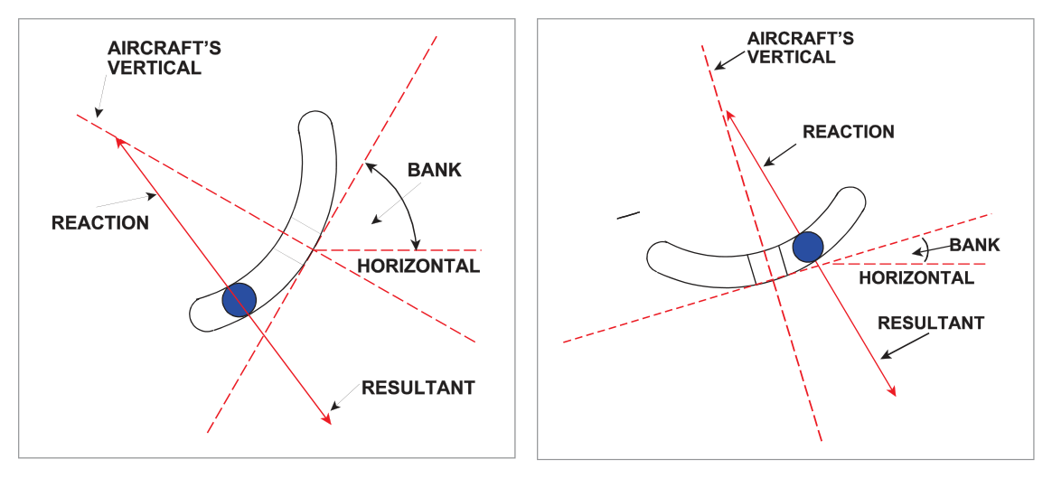
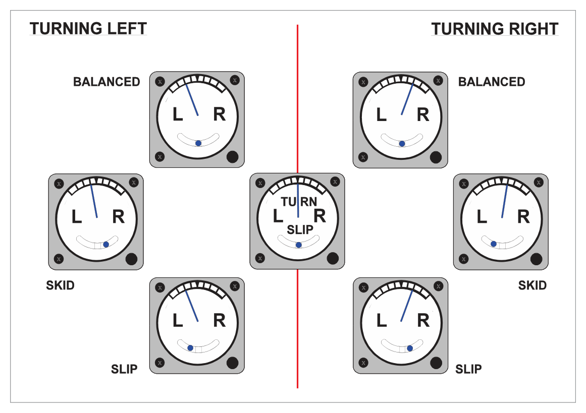
| Inside the turn (e.g. left in left turn) | Slipping in (too much bank; radius too small) | Reduce bank |
| Outside the turn (e.g. right in left turn) | Skidding out (insufficient bank; radius too large) | Increase bank or increase rudder |
Memory aid: "Step on the ball" — apply rudder in the direction the ball has moved to correct the slip/skid.
9. Turn and Slip Displays
The turn indicator needle deflects in the direction of turn (left or right of centre). Rate 1 is indicated at the first marked graduation on each side. The ball shows balanced or unbalanced state as described above.
flowchart LR
    subgraph T[Turn Indicator - Needle]
        NL["Needle Left\n= Left Turn"]
        NC["Needle Centre\n= Straight Ahead"]
        NR["Needle Right\n= Right Turn"]
    end
    subgraph S[Slip Indicator - Ball]
        BL["Ball Left\n= Slipping In\n(left turn - too much bank)"]
        BC["Ball Centre\n= Balanced"]
        BR["Ball Right\n= Skidding Out\n(left turn - too little bank)"]
    end
10. Rate 1 Turn Calculations
Worked Example — Turn Diameter at Rate 1, TAS 360 kt
Given: TAS = 360 kt, Rate 1 turn.
Step 1: Rate 1 = 2 minutes for 360°. At 360 kt, distance in 2 min = 360 × (2/60) = 12 NM. This is the circumference of the turn circle.
Step 2: Circumference = π × d → 12 = (22/7) × d → d = 12 × 7/22 = 3.8 NM
Quick check rule: TAS ÷ 100 ≈ diameter in NM (rough). 360 ÷ 100 = 3.6 NM ✓ (close to 3.8).
Radius: r = d/2 = 1.9 NM
- TAS 360 kt → diameter ≈ 3.8 NM (radius ≈ 1.9 NM)
- TAS 400 kt → diameter ≈ 4.2 NM
- TAS 500 kt → diameter ≈ 5.3 NM
- Quick rule: TAS ÷ 95 ≈ diameter NM
- Rate gyro = horizontal axis, 1 gimbal, 1 DOF. Uses precession (not rigidity) → LOW rotor speed desirable.
- Rate 1 = 3°/sec = 360° in 2 minutes.
- Rate 2 = 6°/sec. Stops limit at ≈20°/sec.
- Calibration TAS: 260 kt. Error ≤5% from 85–350 kt.
- Underspeeding → under-reads turn rate. Overspeeding → over-reads.
- Steep turns → looping plane movement → over-read (sometimes against stops).
- Slip indicator = ball in curved tube. Central = balanced. Inside = slipping. Outside = skidding.
- Bank angle rule of thumb (Rate 1): (TAS ÷ 10) + 7 degrees. Valid 100–250 kt.
- Turn diameter at Rate 1 = TAS ÷ 95 (approx, in NM).
- 1 gimbal only → gyro CANNOT topple even at stops.
Practice Questions & Detailed Answers
- (a) — A space gyro is a free gyro fixed in inertial space, which is not what the rate gyro of the TBI is.
- (b) — A tied gyro is the type used in the DGI and AH, not the rate gyro of the TBI.
- (d) — An earth gyro refers to a gravity-tied gyro (like in the AH). Not applicable here.
- (b) — The TBI does not use the property of rigidity; it uses precession.
- (c) — Higher speed would increase rigidity and reduce sensitivity, the opposite of what is needed.
- (d) — Speed does not vary; it is fixed at a lower value to ensure appropriate sensitivity.
- (b) — The needle showing Rate 1 indicates a rate of turn of 3°/sec which is an airborne turn, not taxiing.
- (c) — Rate 1 (3°/sec) = 360° in 2 minutes, not 1 minute. Rate 2 would be 360° in 1 minute.
- (d) — Needle left = left yaw/turn. "Yawing to the right" is opposite.
- (a) — The spring force acts about the YY axis, not the lateral axis specifically; and "equal to the rate of turn" is dimensionally incorrect — force is not equal to a rate.
- (b) and (c) — "Opposite direction" is incorrect. The spring precession is in the same direction as required for equilibrium with the turning rate.
- (b) — Underspeeding causes UNDER-reading, not over-reading.
- (c) — The indication is affected — it under-reads.
- (d) — Radius of the turn is determined by TAS and rate of turn, not by the indicator's reading. The actual rate of turn and radius are unchanged; only the indication is wrong.
- (a) 10 NM — This would be the circumference at a much slower speed or larger diameter than calculated.
- (b) 5 NM — This would be the diameter, not the radius.
- (c) 7.5 NM — Far too large for Rate 1 at 360 kt.
Master Reference Tables
| Parameter | Value | Section |
|---|---|---|
| Rate 1 turn rate | 3°/second | 3 |
| Rate 1 full circle time | 2 minutes | 3 |
| Rate 2 turn rate | 6°/second | 3 |
| Gimbal stops (max) | ≈20°/second | 4 |
| Calibration TAS | 260 knots | 4 |
| TAS error tolerance | ≤5% from 85–350 kt | 4 |
| Rate 1 bank angle (TAS 150 kt) | 22° | 7 |
| Turn diameter (Rate 1, 360 kt) | ≈3.8 NM | 10 |
| Turn radius (Rate 1, 360 kt) | ≈1.9 NM | 10 |
Answer Key Summary
| Q | Answer | Key Topic |
|---|---|---|
| 1 | c | Rate gyro; spins up and away from pilot |
| 2 | a | Lower rotor speed — high rigidity not needed |
| 3 | a | Needle left + ball left = left turn, slipping in |
| 4 | d | Spring precession = rate of turn, correct direction |
| 5 | a | Blocked filter → underspeeds → under-reads → aircraft turns faster than shown |
| 6 | d | Rate 1, 360 kt → radius ≈ 2 NM |
Reinforce Chapter 14: The Turn and Slip Indicator
Test your knowledge and practice actual exam questions for Navigation — Instrumentation.