The Artificial Horizon
by Ghost Aviator
Table of Contents
- Introduction
- Construction
- Artificial Horizon Indications (Pitch and Roll)
- Limitations
- Control Systems Overview
- The Air Driven Artificial Horizon
- Acceleration Errors — Air Driven AH
- Turning Errors — Air Driven AH
- Rigidity and Serviceability Checks
- The Electric Artificial Horizon
- Electric AH Control System
- Acceleration Errors — Electric AH
- Fast Erection System
- Adjustable Aeroplane Datum
- Vertical Gyro Unit
- Practice Questions & Detailed Answers
- Master Reference Tables
1. Introduction
The Artificial Horizon (AH), also called the gyro horizon or attitude indicator, provides the pilot with information about the aircraft's attitude in both pitch and roll. It is a primary instrument, replacing the natural horizon in poor visibility (IMC).
The attitude display consists of a miniature aircraft shape or 'gull-wing' (tail view) fixed to the instrument case (and thus to the actual aircraft), behind which is a gyro-stabilized horizon bar that remains parallel to the true horizon.
2. Construction
The artificial horizon uses an earth gyro in which the spin axis is maintained in, or tied to, the vertical by earth's gravity. The plane of rotor rotation is therefore horizontal, providing stable lateral and longitudinal references.
3. Artificial Horizon Indications
Pitch
In Figure 13.1 the level-flight attitude is shown. In a nose-up attitude (Figure 13.2), the pitch-up movement rotates the case together with the attached outer gimbal ring about the lateral axis YY. A guide pin from the stabilized inner gimbal forces the horizon bar arm down. The horizon bar is now below the gull-wing → nose-up indication.
In a nose-down attitude (Figure 13.3), the horizon bar appears above the gull-wing.
Roll
As the aircraft rolls about the longitudinal axis (ZZ), the instrument case and gull-wing rotate about the stabilized gyro rotor/gimbal system. Gyroscopic rigidity holds the horizon bar in the rolling plane, displaying the amount and direction of bank of the gull-wing relative to the horizon bar. A pointer attached to the outer gimbal shows bank angle on a scale on the instrument face.
4. Limitations
| Instrument Type | Pitch Limit | Roll Limit |
|---|---|---|
| Older designs | ±60° | ±110° |
| Modern instruments | ±85° | 360° (complete freedom) |
If limits are exceeded, the gyro topples, giving violent and erratic movements of the horizon bar. Without a fast erection system, accurate indications will not be obtained until the gyro re-erects itself over a period of 10 to 15 minutes.
5. Control Systems Overview
The rotor assembly is made very slightly bottom-heavy to keep down the time for initial erection when first started up. The erection system then maintains the rotor axis vertical in flight.
| AH Type | Erection Method | Rotor Speed |
|---|---|---|
| Air Driven (Suction) | Four pendulous vanes + four slots | Up to 15,000 rpm |
| Electric | Mercury/levelling switches + torque motors | Typically 22,500 rpm |
6. The Air Driven Artificial Horizon
An engine-driven suction pump (or venturi tube in some light aircraft) creates a suction of about 4 inches of mercury in the instrument case. Replacement air drawn in via a filter is ducted through the outer and inner gimbals to enter the rotor case as a jet which spins the rotor at up to 15,000 rpm.
Control System — Pendulous Vanes
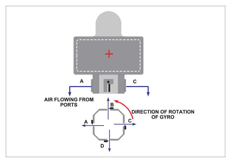
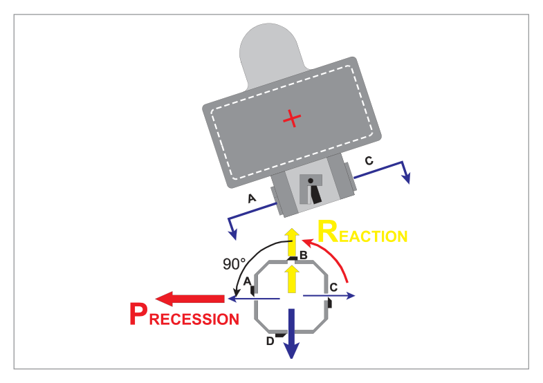
Four slots and four pendulous (hanging) vanes are at the base of the rotor housing. When the rotor axis is vertical, each slot is half covered by its vane, producing four equal jets fore, aft, left and right. Equal and opposite jets produce no net force → no precession → rotor remains vertical.

The opposing vanes are fixed to a common spindle operating as two pairs. If the rotor axis wanders from the vertical, one vane hangs clear of its slot (fully open) while the opposite slot is completely obstructed. The resulting unbalanced airflow jet produces a reaction that is precessed through 90° in the direction of rotor spin, correcting the tilt and returning the gyro axis to the vertical.
7. Acceleration Errors — Air Driven AH
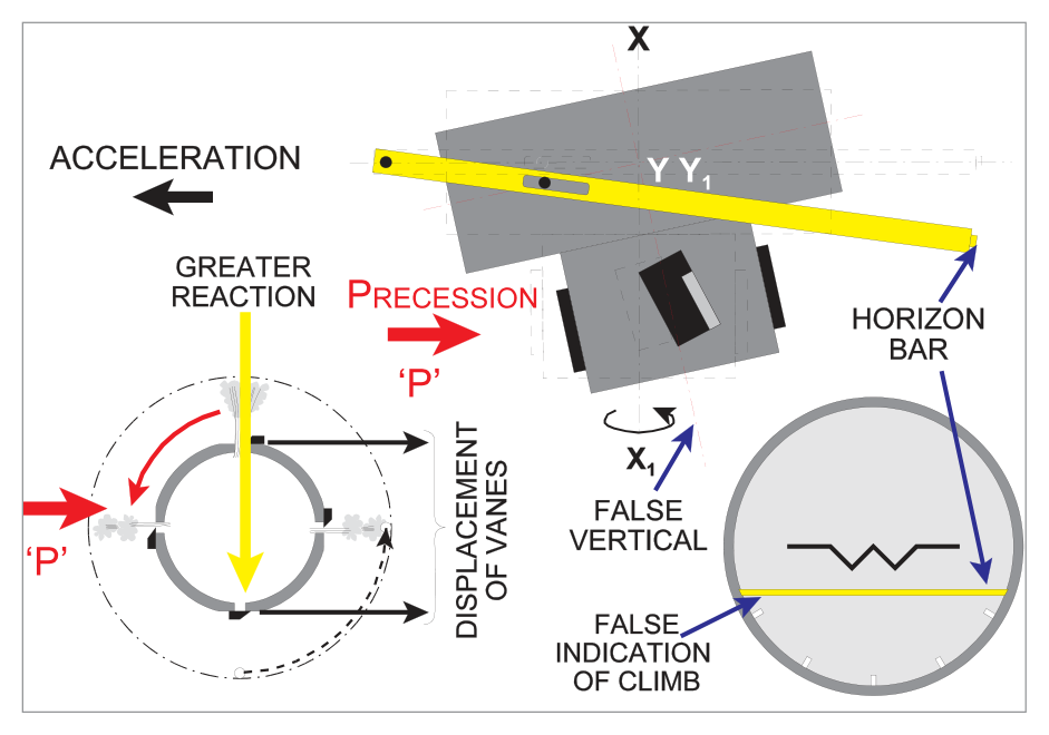
The control system depends on gravity acting on the pendulous vanes. Any acceleration (not just gravity) will affect the vanes, causing false indications.
Pitch Error During Acceleration
During acceleration, the lateral vanes lag (swing back towards the pilot), opening the starboard slot and closing the port slot. The resulting reaction R acts to port. By the rule of precession, this is precessed 90° in the direction of rotor spin (anticlockwise when viewed from above), causing the gyro base to move backwards. The horizon bar drops below the gull-wing → false nose-up indication.
Roll Error During Acceleration
Due to inertia, the weighted (bottom-heavy) base of the rotor housing tries to lag during acceleration. This force is precessed, resulting in the base of the rotor housing moving to starboard and the gyro axis precessing out of vertical → false right wing down indication.
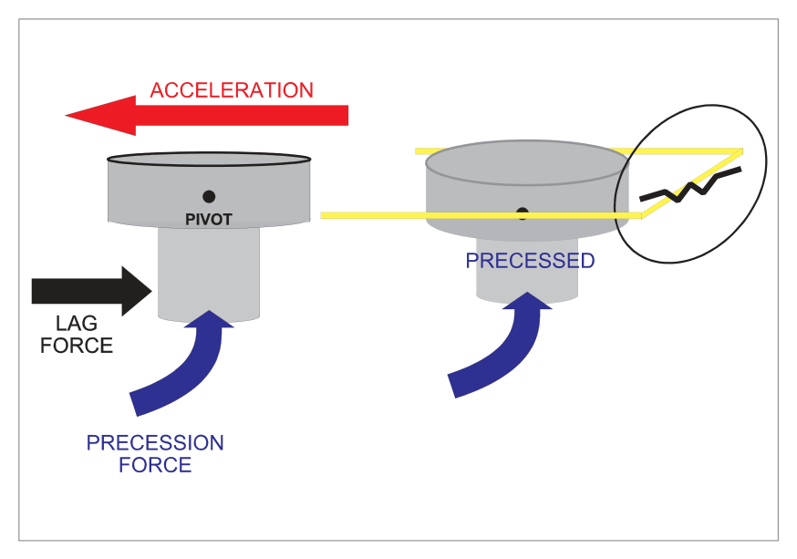
- Acceleration → false nose-UP, right wing DOWN (British/anticlockwise rotor).
- Deceleration → opposite: false nose-DOWN, left wing LOW.
- American air-driven / most electric horizons rotate clockwise → give opposite errors.
8. Turning Errors — Air Driven AH
During turns, centripetal acceleration acts on the pendulous vanes (erection error) and the weighted base of the rotor housing (pendulosity error). The errors are complex and change as the turn progresses, cancelling out after a 360° turn.
| Turn Completed | Bank Indication | Pitch Indication |
|---|---|---|
| 90° | Under-reads bank angle | Indicating a climb |
| 180° | Bank angle correct | Indicating a climb |
| 270° | Over-reads bank angle | Indicating a climb |
| 360° | Bank angle correct | Pitch angle correct |
Compensation is applied by tilting the top of the rotor axis slightly forward (for erection error) and slightly to the left (for pendulosity error) — tilts of the order of 2°. The horizon bar setting is similarly modified.
9. Rigidity and Serviceability Checks
| AH Type | Rotor Speed | Gyroscopic Inertia |
|---|---|---|
| Suction AH | Up to 15,000 rpm | High |
| Electric AH | Typically 22,500 rpm | Even greater |
- Check that the horizon bar takes up a laterally level position with the correct pitch indication for the aircraft type.
- Confirm indication is maintained when taxiing.
- If a caging device is fitted, uncage at least 5 minutes before take-off to ensure the rotor axis has reached alignment with the true vertical.
10. The Electric Artificial Horizon
The main advantage of the electric artificial horizon is its greater rigidity due to its faster spin rate (22,500 rpm typical vs. 15,000 rpm for suction). This results in increased accuracy due to reduced errors. The basic principle (earth gyro, tied to vertical) is the same as the air-driven horizon.
The vertical gyro is tied to the vertical by mercury / levelling switches and torque motors rather than the pendulous vanes of the air-driven horizon.
11. Electric AH Control System
The gravity-operated control system uses mercury / levelling switches fixed to the base of the rotor and electric torque motors. If a levelling switch is not level, the mercury liquid ball moves from its central position and closes the circuit to drive its torque motor. The torque motor force is precessed to return the gyro axis to the vertical.
There are two levelling switches — one sensing pitch, one sensing roll — activating their respective torque motors.
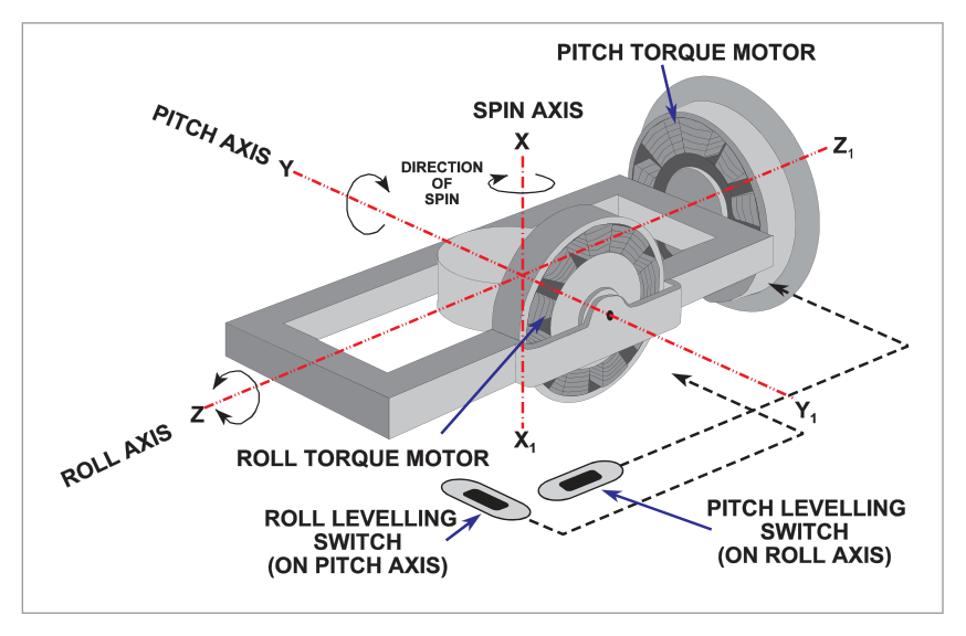
Due to the 90° precession rule:
- Torque motor on the side of the inner gimbal corrects wander in the rolling plane.
- Torque motor on the outer (longitudinal) gimbal corrects wander in the pitch plane.
12. Acceleration Errors — Electric AH
- High rotor speed → very high gyro rigidity → very low precession rates → less tendency for gyro to move out of vertical.
- Less bottom-heavy rotor housing → reduced roll error during acceleration.
- Pitch cut-out switch: Activates at acceleration of 0.18g or greater — disconnects the pitch levelling switch circuit to prevent false precession.
- Roll cut-out switch: Activates at 10° angle of bank — prevents the roll mercury switch from falsely activating the roll torque motor during turns.
13. Fast Erection System
Many electric horizons include a fast erect system for rapid initial erection and quick re-erection after toppling. The fast erection knob increases voltage to the erection torque motors:
| Mode | Erection Rate |
|---|---|
| Normal | 4° per minute |
| Fast erect (knob pushed) | 120° per minute |
14. Adjustable Aeroplane Datum
Found on some American artificial horizons, this refinement allows the 'aeroplane' datum to be adjusted to lie on the horizon if the aircraft has a pitch-up trimmed attitude in level flight.
15. Vertical Gyro Unit
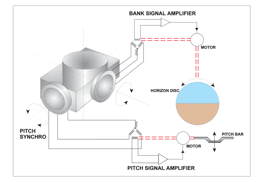
The Vertical Gyro Unit (VGU), also called the remote vertical gyro or vertically axised data generation unit, performs the same function as the gyro horizon — it establishes a stabilized reference about the pitch and roll axes. However, instead of providing attitude displays directly to a dial, it operates an electrical transmission system to a steering computer, which displays the output on a combined attitude indicator and flight director display.
flowchart LR
    VGU["Vertical Gyro Unit\n(remote gyro)"] --> SC["Steering Computer"] --> EADI["Combined Attitude &\nFlight Director Display"]
    DI["Direct AH\n(conventional)"] --> Pilot["Pilot's Instrument Panel\n(direct reading)"]
- AH = earth gyro, spin axis tied to vertical. Primary attitude instrument.
- Air-driven: suction ≈4 inHg; rotor to 15,000 rpm; 4 pendulous vanes.
- Electric: mercury switches + torque motors; rotor ≈22,500 rpm; greater rigidity.
- Acceleration error (air-driven, anticlockwise rotor): Nose-UP + Right wing DOWN.
- Deceleration: opposite — nose-down + left wing low.
- Turning errors: cancel after 360°; compensated by ≈2° tilt of rotor axis.
- Electric AH: pitch cut-out at 0.18g; roll cut-out at 10° bank.
- Fast erect: normal 4°/min → fast 120°/min. Only use in level, unaccelerated flight.
- Older AH limits: ±60° pitch, ±110° roll. Modern: ±85° pitch, 360° roll.
- Re-erection without fast erect: 10–15 minutes.
- Uncage caging device: ≥5 minutes before take-off.
- EASA: adjustable datum inoperative above 6,000 lb MTOW.
Practice Questions & Detailed Answers
- (a) — "Position," "latitude," and "longitude" describe a navigation instrument, not an attitude indicator.
- (b) — A "space gyro" is a free gyro fixed in space — the AH uses an earth gyro tied to the vertical by gravity.
- (c) — Correct gyro type but "latitude" is wrong; it shows attitude in pitch and roll.
- (a) — "Left bank" is incorrect; acceleration gives right wing down (starboard bank) error.
- (b) — "Descending" and "to the right" are both wrong; the indication is climbing (nose up) and right wing down, but not a turn.
- (d) — "Left" is incorrect; the bank error is to the right.
- (a) — "Climbing" and "right" — pitch and bank are both opposite.
- (b) — "Left wing down" would mean starboard bank; the display shows port bank.
- (c) — "Starboard" is incorrect; gull-wing tilts right = port bank.
- (a) — High pendulosity of the rotor housing causes the roll error (right wing down), not the pitch error.
- (c) — The linear acceleration cut-out is a feature of the electric AH, not the air-driven type, and it would reduce errors, not cause them.
- (d) — Incorrect rotor speed affects rigidity and precession rate but is not the cause of the specific acceleration pitch error.
- (a) — Four pendulous vanes are the erection method of the air-driven AH, not the electric.
- (b) — The roll cut-out is a safety feature to prevent false erection during turns, not the erection system itself.
- (c) — The low centre of gravity (bottom-heaviness) assists initial erection but is not the erection control system.
- (b) — The longitudinal pendulous vanes cause the pitch error (nose-up), not the roll error.
- (c) — The roll cut-out is an electric AH feature and reduces (not causes) errors.
- (d) — High rotor speed increases rigidity and reduces errors; it does not cause roll error.
- (b) — It is the rotor axis (via gimbals) that is tied to the vertical by the control system, not the inner gimbal ring directly.
- (c) — Springs are used in the rate gyro (turn indicator), not the AH erection system.
- (d) — The AH has two gimbal rings (inner and outer), not one.
- (a) — Regular in-flight checking/adjusting is the risk — it should be set before flight and not touched again.
- (c) — This applies to aircraft over 6,000 lb MTOW (EASA requirement), not to light aircraft specifically. The question specifies light aircraft.
- (d) — 15° has no relevance to the datum setting procedure.
- (b) — Greater sensitivity of mercury switches would worsen acceleration errors, not reduce them. The cut-outs are needed specifically because the switches can be too sensitive.
- (c) — The roll cut-out activates at 10° bank (during turns), not during the take-off run (linear acceleration).
- (d) — "Aperiodicity" is a compass term (damping ratio). Not applicable here.
Master Reference Tables
| Parameter | Air-Driven AH | Electric AH |
|---|---|---|
| Erection method | 4 pendulous vanes + slots | Mercury switches + torque motors |
| Rotor speed | Up to 15,000 rpm | ≈ 22,500 rpm |
| Pitch limit (older) | ±60° | ±85° (modern) |
| Roll limit (older) | ±110° | 360° (modern) |
| Pitch cut-out | None | 0.18g |
| Roll cut-out | None | 10° bank |
| Normal erection rate | Slow | 4°/min |
| Fast erection rate | N/A (cage) | 120°/min |
| Re-erection time (no fast) | 10–15 min | 10–15 min |
| Suction (air-driven) | ≈4 inHg | N/A |
Acceleration Error Summary
| Event | British Air-Driven (CCW rotor) | American/Electric (CW rotor) |
|---|---|---|
| Acceleration (take-off) | Nose-UP + Right wing DOWN | Nose-UP + Left wing DOWN |
| Deceleration | Nose-DOWN + Left wing LOW | Nose-DOWN + Right wing LOW |
Answer Key Summary
| Q | Answer | Key Topic |
|---|---|---|
| 1 | d | Earth gyro; shows attitude in pitch and roll |
| 2 | c | Acceleration → nose-up + right wing down |
| 3 | d | 30° port bank, nose below horizon |
| 4 | b | Pitch error = lag of lateral pendulous vanes |
| 5 | d | Electric: 2 mercury switches + 2 torque motors |
| 6 | a | Roll error = lag of bottom-heavy rotor housing base |
| 7 | a | Inner gimbal lateral; outer gimbal longitudinal |
| 8 | b | Light aircraft: set before flight, leave alone |
| 9 | a | Less pendulous + higher RPM + pitch cut-out |
Reinforce Chapter 13: The Artificial Horizon
Test your knowledge and practice actual exam questions for Navigation — Instrumentation.