Directional Gyro Indicator (DGI)
by Ghost Aviator
Table of Contents
- Introduction
- Principle and Construction of the DGI
- Control System — Suction Gyros
- The Caging Device
- DGI Limitations
- DGI Errors
- Gimballing Errors
- Random Wander
- Apparent Wander (Earth's Rotation)
- Latitude Nut Correction
- Effect of Latitude Change on Compensated DGI
- Errors Due to Unstable Rotor RPM
- Transport Wander
- Drift Rate Calculations
- Practice Questions & Detailed Answers
- Master Reference Tables
1. Introduction
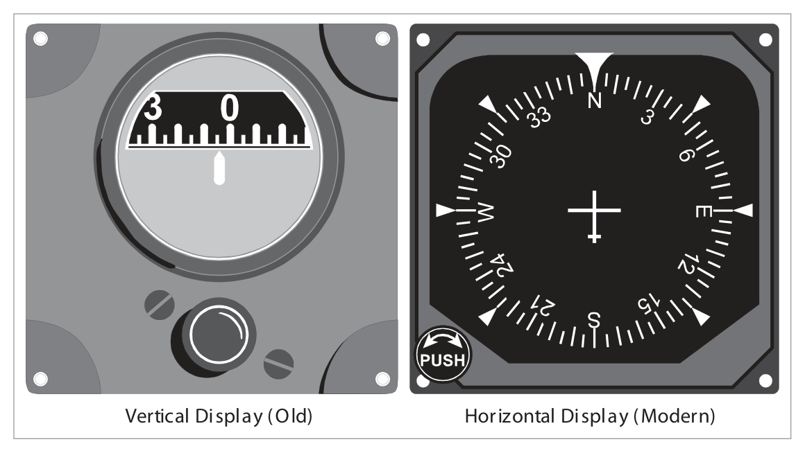
The Directional Gyro Indicator (DGI), also called the Direction Indicator (DI), provides a stable directional reference in azimuth for maintaining accurate headings and executing precise turns.
There is no magnetic element in the DI, so it is not north-seeking and must initially be synchronized with the magnetic compass. Synchronization must be checked at regular intervals because of real and apparent gyro wander (drift). The DGI does not replace the compass — its stable, dead-beat indications are complementary to the north-seeking capability of the compass.
Having no magnetic element, the DGI does not suffer from the compass turning and acceleration errors produced by the vertical component of the earth's magnetic field.
2. Principle and Construction of the DGI
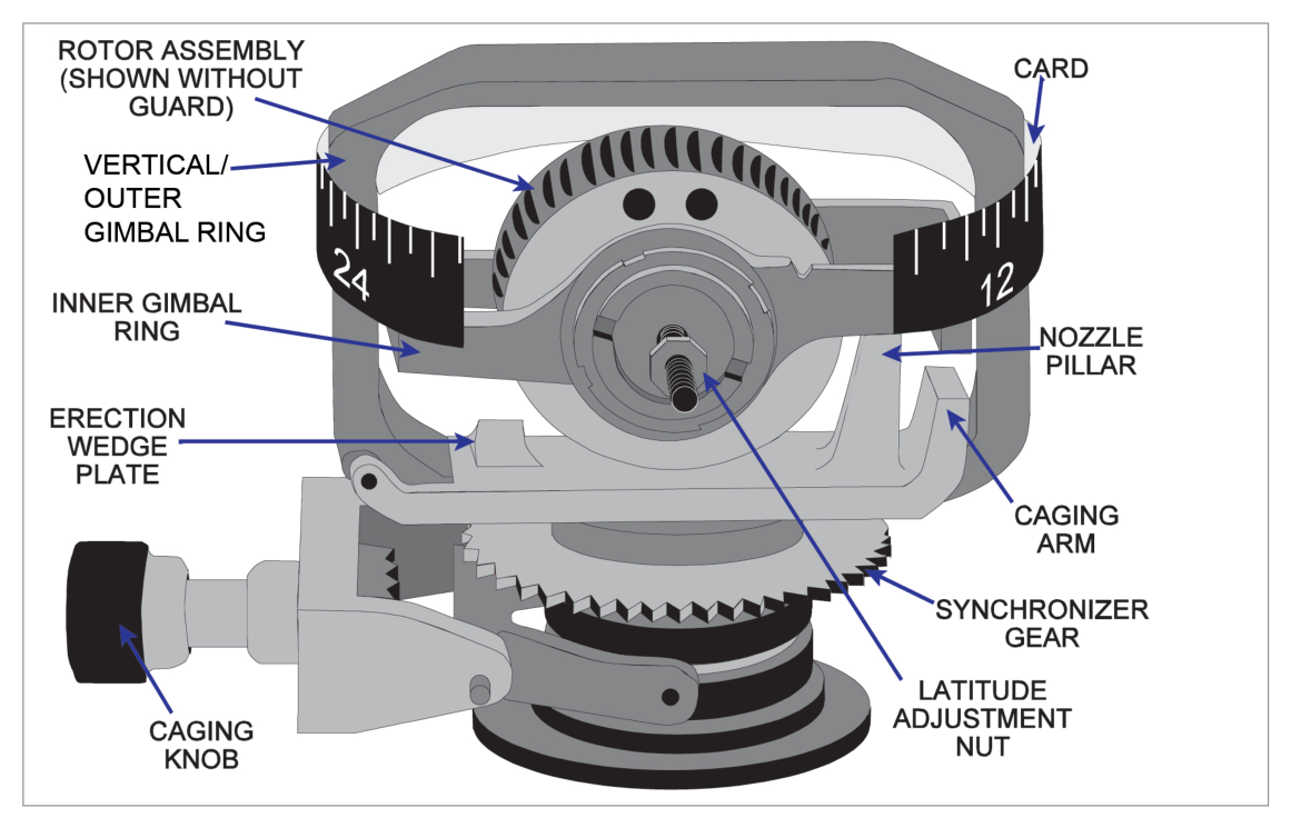
The DI employs a tied gyro — a gyro having freedom of movement in three planes mutually at right angles, but with the rotor axis maintained in the yawing plane of the aircraft. This means the rotor axis is horizontal in level flight, and gyroscopic rigidity provides the datum from which heading is measured.
The rotor is mounted in the inner gimbal (on bearings in the outer gimbal), which has restricted freedom to turn. The outer gimbal can rotate through 360° about the aircraft's vertical axis, on bearings in the case.
Note that the rotor axis, inner gimbal axis, and outer gimbal axis are mutually at right angles.
During a turn, the aircraft and instrument case turn on the vertical axis bearings of the outer gimbal whilst the gyro rotor, gimbals and indicating scale all remain fixed in azimuth because of gyroscopic rigidity. Heading is indicated on the scale by a lubber line painted on a glass window in the instrument case.
3. Control System — Suction Gyros
With earlier designs of DGI, the rotor is driven by twin jets of air applied from the outer gimbal ring. Suction is applied to the case; replacement air enters through a filter and is ducted to jets on the outer gimbal which act on 'buckets' cut in the rotor.
The jets not only spin the rotor but also serve to maintain or tie the rotor axis in the yawing plane.
First Control System — Air Jet Erection
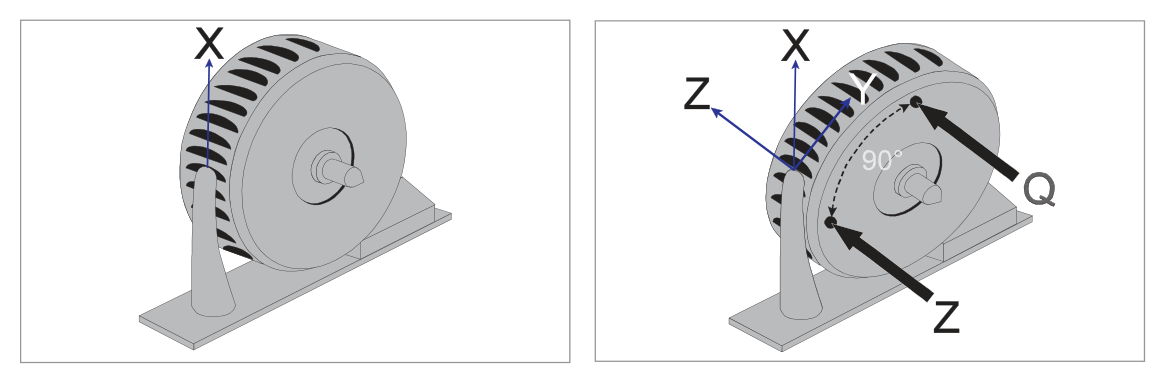
When the rotor axis is in the yawing plane, the full force X of the jets drives the rotor. If the aircraft banks, gyroscopic rigidity keeps the rotor axis fixed in space — it is no longer in the yawing plane. Force X is then resolved into:
- Component Y — in the plane of rotation, maintaining spin.
- Component Z — acting at 90° to the plane of rotation.
Because this is a gyro, Component Z precesses the rotor as if it were applied 90° around the circumference in the direction of spin. The result is a force Q operating to re-erect the rotor with its axis in the yawing plane.
Second Control System — Wedge Plate
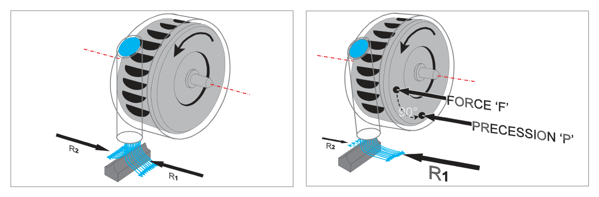
Air spinning the rotor flows round the rotor inside a metal case and is directed at a wedge plate fixed to the outer gimbal. When the gyro is correctly erected, the exhaust jet is divided into two equal streams producing equal reactions (R1 & R2) on the outer gimbal. When the rotor axis is displaced from the yawing plane, streams become unbalanced, producing an unequal reaction that applies a torque to the outer gimbal about the vertical gyro axis. This torque is precessed to re-erect the rotor axis.
4. The Caging Device
On the front of the instrument there is a caging knob which, when pushed in, moves a caging arm that locks the inner gimbal at right angles to the outer gimbal (locking the rotor axis in the yawing plane). A gear simultaneously engages with the outer gimbal so that turning the knob rotates the gyro and synchronizes the scale reading with (usually) the compass reading.
- Allows synchronization of the DGI with the compass and resetting as required.
- Prevents the gyro from toppling during synchronization.
- Prevents toppling and possible damage before manoeuvres in which pitch and roll limits may be exceeded.
- Allows instant re-erection and re-synchronization if the gyro has toppled.
5. DGI Limitations
- Air driven DGI: 55° pitch / roll limit.
- Modern DGI: 85° pitch / roll limit.
When toppled, the inner gimbal hits its stops, causing precession that makes the outer gimbal and scale spin rapidly.
Exceptions to toppling:
- If the rotor axis is athwartships — 360° of aircraft rotation in the looping plane is then possible without toppling.
- If the rotor axis is fore and aft — 360° of roll is then possible without toppling.
6. DGI Errors — Summary
There are several reasons why it is virtually impossible for a DGI to remain synchronized with the compass. The most significant errors are:
- Gimballing errors.
- Random wander.
- Apparent wander due to earth's rotation.
- Errors resulting from varying rotor rpm.
- Apparent wander due to change of aircraft position (transport wander).
flowchart TD
    A[DGI Errors] --> B[Gimballing Errors\nDue to gimbal geometry\nin banked turns]
    A --> C[Random Wander\nReal wander from\nmanufacturing imperfections]
    A --> D[Apparent Wander\nDue to Earth's rotation\n15 × sin lat °/h]
    A --> E[Unstable Rotor RPM\nAffects precession rate\nand latitude correction]
    A --> F[Transport Wander\nMovement between\nnon-parallel meridians]
7. Gimballing Errors
Gimballing errors are errors in DGI indications which occur when bank is applied. If the errors during a 360° turn are plotted, an approximate double sine curve results, with zero error on four headings (90° apart) spaced between alternate positive and negative peaks (two of each).
The errors are small provided deviations in attitude from level are only moderate, and they disappear as soon as level flight is resumed. They occur because of the geometry of the gimbal system — unless the instrument case (and aircraft) can rotate about one of the gyro axes, the outer gimbal itself must move (giving an error) if the rotor axis is to maintain its fixed direction.
8. Random Wander
The gyro rotor axis may change its direction in space (real wander) or appear to change direction (apparent wander). Random wander (or drift) is mainly due to manufacturing imperfections.
| DGI Type | Rotor Speed | Drift Rate |
|---|---|---|
| Air driven (older) | 10,000 rpm | ≈ 1.6°/hour |
| Air driven (later) | 20,000 rpm | ≈ 1.2°/hour |
| Electrically driven | Higher speeds | A few °/hour |
| Inertial navigation gyros | Very high | < 0.01°/hour |
9. Apparent Wander Due to Rotation of the Earth
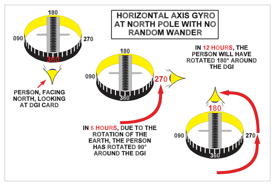
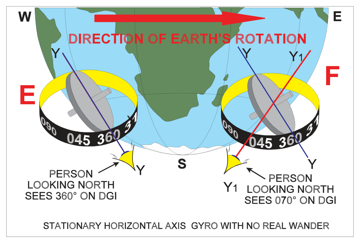
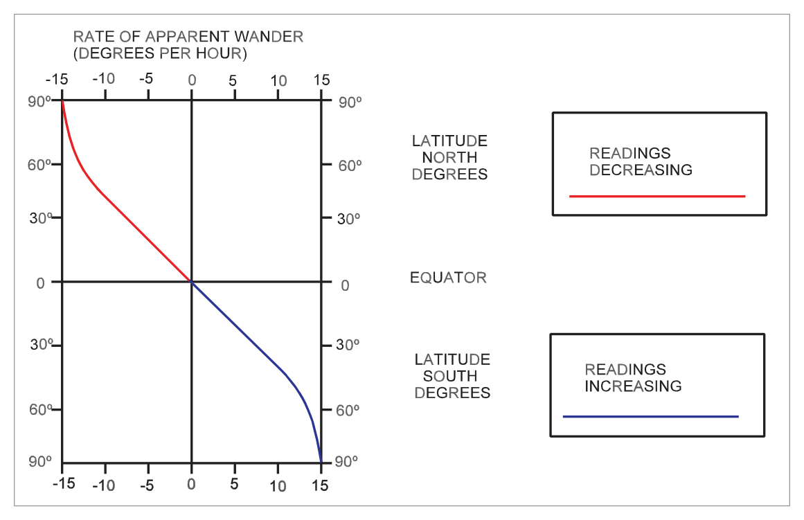
An azimuth gyro at the North Pole (rotor axis horizontal) will have its reading decrease at a rate of 15°/hour (at the South Pole, the reading increases at the same rate). This is the maximum apparent drift rate.
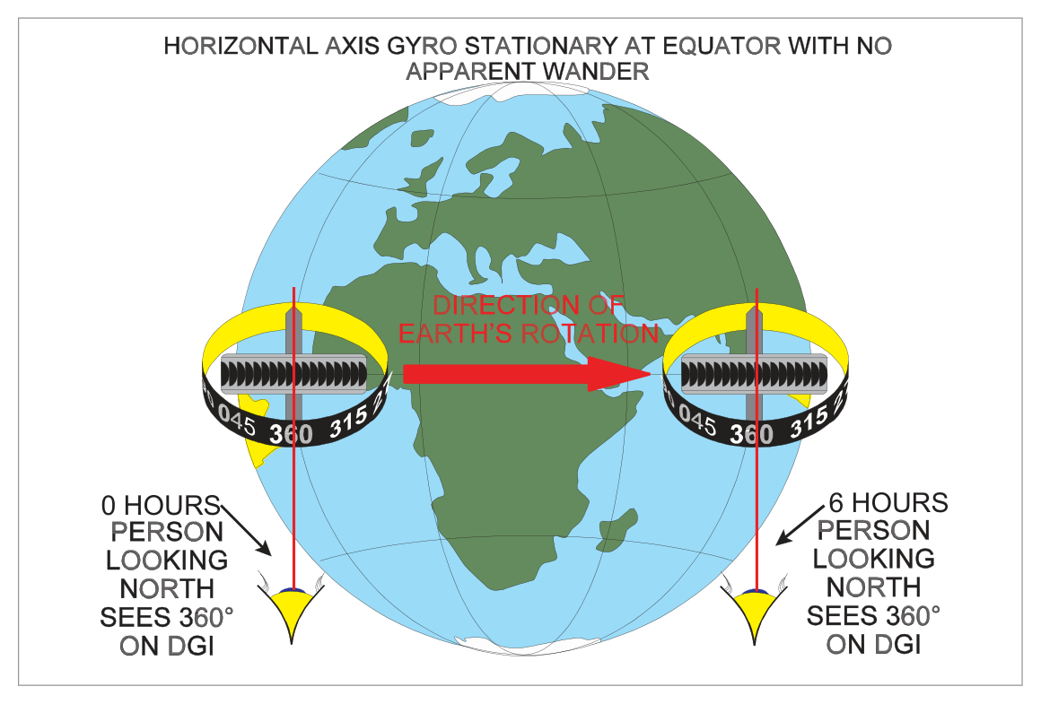
At the equator, an observer and gyro aligned N/S will move with the earth through 360° in 24 hours with no change in rotor axis direction relative to the meridian — so there is zero apparent drift at the equator.
Sign convention:
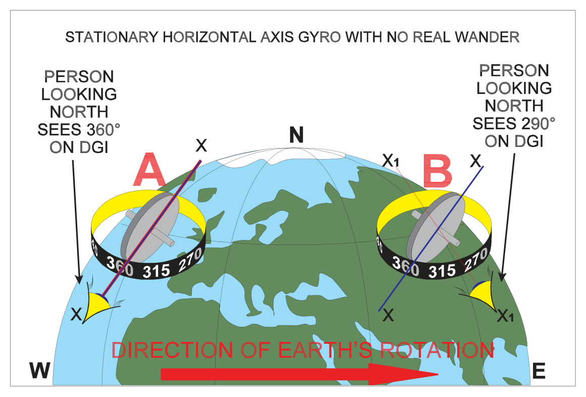
- Northern hemisphere: DGI reading decreases (negative drift).
- Southern hemisphere: DGI reading increases (positive drift).
10. Latitude Nut Correction
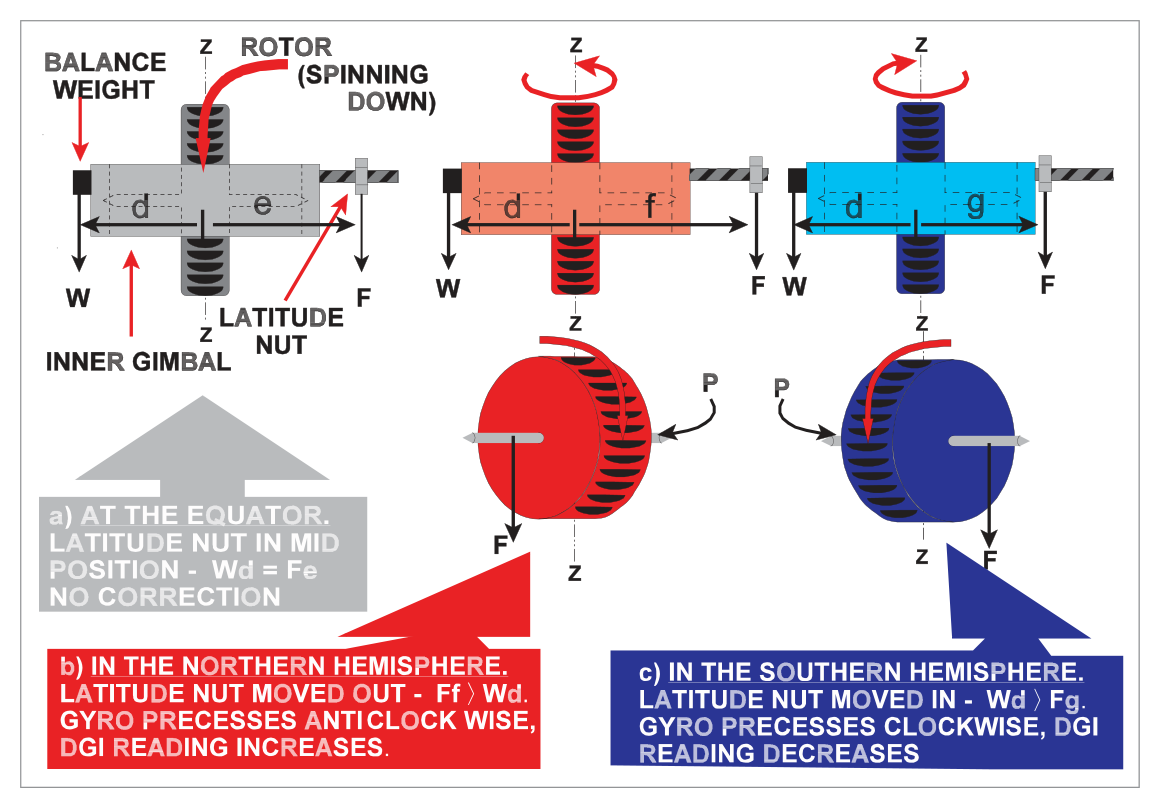
Compensation for apparent wander due to the earth's rotation is by means of an adjustable latitude rider nut on a threaded stud fixed horizontally to the inner gimbal.
In its central position, the effect of the nut is cancelled by a counter-balance weight on the opposite side of the gimbal.
- Screwed out: Applies a downward moment → anticlockwise precession (viewed from above) → DGI reading increases.
- Wound in: Clockwise precession → DGI reading decreases.
This enables compensation for both increasing readings (southern hemisphere) and decreasing readings (northern hemisphere).
Effect of Latitude Correction on Gyro Behaviour
Figure 12.13 illustrates the effect of compensating a gyro for apparent drift of −13°/h at 60°N (= 15 sin 60°). The latitude nut introduces a real drift of +13°/h so the resultant drift is zero at 60°N.
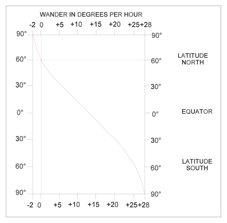
- Flight north from the corrected latitude → DGI reading decreases (minus drift rate).
- Flight south from the corrected latitude → DGI reading increases (plus drift rate).
- Flight away from the corrected latitude → drift rate increases.
- Flight towards the corrected latitude → drift rate decreases.
11. Effect of Change of Aircraft Latitude on Compensated DGI
The apparent drift rate varies with the sine of latitude. Consider a flight due north starting from the equator:
- At equator: drift rate = 0°/h
- At 30°N: drift rate = 7.5°/h (decreasing)
- At 60°N: drift rate = 13°/h (decreasing)
- At 90°N (pole): drift rate = 15°/h (decreasing)
The rate of increase of drift rate is not linear — it follows the sine function. The same applies to a compensated gyro moving north or south from its correction latitude.
12. Errors Due to Unstable Rotor RPM
Since the precession rate depends on rotor rpm, over which no precise control is maintained in a suction-driven DGI, latitude nut compensation is only approximate.
| Condition | Effect on RPM | Effect on Rigidity | Result |
|---|---|---|---|
| High altitude / choked filter / leaking suction | Below design value (underspeeding) | Reduced | Latitude nut over-corrects apparent drift |
| RPM exceeds design figure | Above design value (overspeeding) | Increased | Latitude nut under-corrects apparent drift |
13. Transport Wander
At any latitude other than the equator, meridians (which define local north) are not parallel. If the gyro is aligned to one meridian, then the aircraft is flown east to west, the new meridian will be inclined to the old one by an amount known as transport wander.
14. Drift Rate Calculations
Variables: 15 = earth's rotation rate in °/hour; latitude = aircraft's latitude in degrees.
Sign: Negative (reading decreases) in northern hemisphere; positive (reading increases) in southern hemisphere.
Worked Example 1
Problem: An aircraft is stationary at 60°N. Calculate the hourly wander rate for an uncompensated gyro.
Solution:
Apparent wander = −15 × sin 60° °/h = −15 × 0.866 = −12.99°/h (reading decreases)
Worked Example 2
Problem: A DGI is compensated for 56°N. The aircraft is now at 30°N. What is the residual drift rate?
Solution:
Correction applied at 56°N = +15 × sin 56° = +15 × 0.829 = +12.44°/h (real drift introduced by latitude nut)
Apparent drift at 30°N = −15 × sin 30° = −15 × 0.5 = −7.5°/h
Residual drift = +12.44 − 7.5 = +4.94°/h (reading increases — over-corrected)
- DGI = tied gyro, rotor axis in yawing plane. No magnetic element — must sync with compass.
- Air jets: coarse erection. Wedge plate: fine erection.
- Topple limits: 85° modern / 55° air-driven DGI (pitch and roll).
- Apparent drift = 15 × sin lat °/h. Negative in NH (decreasing), positive in SH (increasing).
- Zero drift at equator; max 15°/h at poles.
- Latitude nut: workshop adjustment only. Screwed out → reading increases; wound in → decreases.
- Transport wander: apparent drift due to movement between non-parallel meridians.
- Gimballing errors: disappear on return to level flight; double sine curve over 360° turn.
- Air-driven DGI: 10,000 rpm → 1.6°/h drift; 20,000 rpm → 1.2°/h drift.
- INS gyros: < 0.01°/h drift.
Practice Questions & Detailed Answers
- (a) — An earth gyro is free to orientate itself relative to the earth's gravity — the DGI is tied, not free.
- (c) — The spin axis of the DGI is horizontal (in the yawing plane), not vertical. A vertical axis would describe the artificial horizon.
- (d) — Tied is correct but vertical axis is wrong for the same reason as (c).
- (a) — In NH, apparent drift causes a decrease (anticlockwise). The correction must produce the opposite (increase/clockwise) — so "clockwise" alone is actually in the right direction but this option is incomplete and misleading, plus (d) is the precise mechanism.
- (b) — Precessing in the same direction as apparent wander would amplify the error, not correct it.
- (c) — Air jets are part of the erection system to keep the rotor in the yawing plane, not for apparent wander correction.
- (a) — Flying north, apparent drift increases (more negative), exceeding the latitude nut correction. Net drift is negative (DGI reads lower). To maintain constant DGI, the pilot turns eastward — true heading increases, not decreases.
- (b) — Flying east changes longitude but not latitude significantly, so apparent drift remains approximately the same as at 56°N and the net is near zero. True heading would not drift consistently.
- (d) — Flying west is similar to (b) for the same reason.
- (a) and (b) — Positive sign is incorrect for the northern hemisphere (positive would apply in the southern hemisphere).
- (d) — "Increasing" is incorrect; in the NH the DGI reading decreases (the drift is negative).
- (a) — "Acceleration error" and "turning error" are compass errors, not DGI errors. The DGI is unaffected by the vertical component of earth's field.
- (c) — "Looping error" and "rolling error" are not standard DGI error categories.
- (d) — "Latitude error" and "turning error" are not in the standard list; "latitude error" is subsumed under apparent wander.
- (a) — "Horizontal plane" is too vague; "yawing plane" is the precise term. Also "wedge plate" alone is fine adjustment, not the primary method.
- (b) — "Vertical plane" is wrong — that would describe the AH rotor axis.
- (d) — "Wedge plate" is used with air-driven, but for electrical DGIs the torque motor is the correct answer, not wedge plate.
- (a) — Partially correct but incomplete; it also resets heading.
- (b) — Partially correct but incomplete; it also prevents toppling.
- (d) — Apparent wander is corrected by the latitude nut, not the caging knob.
- (a) — The inner gimbal holds the rotor; it doesn't carry the driving jets.
- (c) — The casing holds the suction port (inlet side), not the jets themselves.
- (d) — The rotor axis is what the jets act upon (via the buckets), not where they are attached.
- (a) and (b) — Mixes the old (55°) and modern (85°) limits. Neither combination is correct for a single type of instrument.
- (c) — 55° both ways applies to the older air-driven DGI, not the modern one.
- (b) — Gimballing error is self-correcting when level flight is resumed; no gyro reset is needed.
- (c) — Gimballing errors occur in any banked manoeuvre, not only in 360° turns.
- (d) — The error is zero on four headings (90° apart), not two.
Master Reference Tables
Numerical Values Quick Reference
| Parameter | Value | Section |
|---|---|---|
| Earth's rotation rate | 15°/hour | 9 |
| Maximum apparent drift (poles) | 15°/hour | 9 |
| Apparent drift at equator | 0°/hour | 9 |
| Apparent drift formula | 15 × sin(lat) °/h | 9 |
| Modern DGI topple limit (pitch & roll) | 85° | 5 |
| Air-driven DGI topple limit | 55° | 5 |
| Air-driven DGI drift (10,000 rpm) | ≈ 1.6°/h | 8 |
| Air-driven DGI drift (20,000 rpm) | ≈ 1.2°/h | 8 |
| INS gyro drift | < 0.01°/h | 8 |
| Normal RIMC precession rate | ≈ 3°/min | — |
| Latitude nut latitude change for substitution | ≈ 60° | 10 |
Answer Key Summary
| Q | Answer | Key Topic |
|---|---|---|
| 1 | b | DGI is a horizontal axis tied gyro |
| 2 | d | Latitude nut precesses opposite to apparent wander |
| 3 | c | Flying south → DGI over-corrects → true heading decreases |
| 4 | c | NH drift = −15 sin lat °/h |
| 5 | b | 5 DGI errors: Gimballing, Random, Apparent, RPM, Transport |
| 6 | c | Yawing plane; air jets; torque motor (electrical) |
| 7 | c | Caging = reset heading AND prevent toppling |
| 8 | b | Air jets attached to outer gimbal |
| 9 | d | Modern DGI: 85° pitch AND roll |
| 10 | a | Gimballing errors disappear on return to level flight |
Reinforce Chapter 12: Directional Gyro Indicator (DGI)
Test your knowledge and practice actual exam questions for Navigation — Instrumentation.