Gyroscopes
by Ghost Aviator
Table of Contents
- Gyroscopes – Introduction and Basic Properties
- Rigidity
- Gimbals and Degrees of Freedom
- Precession
- Relationship Between Precession and Rigidity
- Wander – Drift and Topple
- Real and Apparent Wander
- Earth Rate
- Transport Wander
- Types of Gyro – by Function
- Types of Gyro – by Construction
- Suction vs. Electric Power
- Gimbal Lock
- Practice Questions & Detailed Answers
- Master Reference Tables
1. Gyroscopes – Introduction and Basic Properties
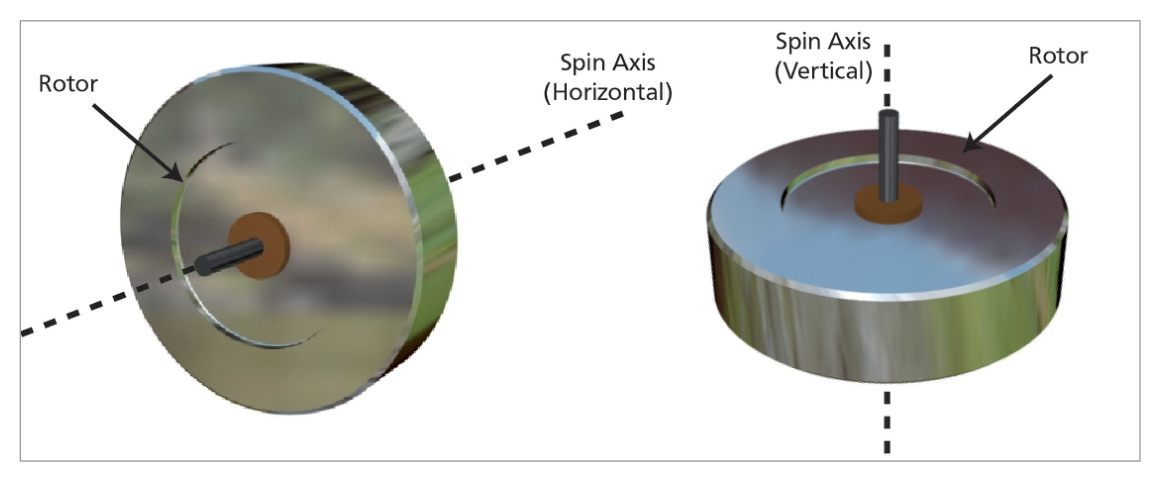
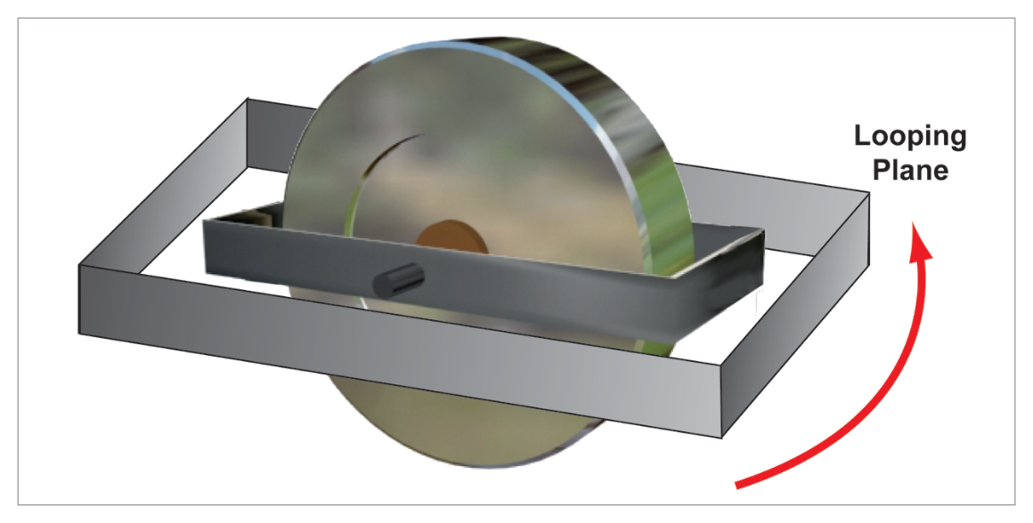
The simplest gyroscope (gyro) is a rapidly spinning disc (rotor). Any rapidly spinning symmetrical rotor exhibits gyroscopic properties — including the earth, spinning tops, and bicycle wheels.
The shaft about which the rotor spins is the axis. Gyros are defined as horizontal or vertical by reference to the spin axis (not the rotor face).
- Rigidity — the tendency to maintain the spin axis direction in space
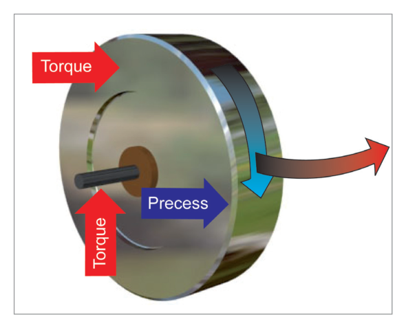
- Precession — the response to an applied force, at 90° in the direction of rotation
2. Rigidity
The words "fixed direction in space" are critical — the gyro points to a fixed point in the universe (e.g. a distant star), irrespective of earth rotation or aircraft motion. Over short periods this distinction from "fixed in earth terms" may not matter, but it becomes critical for long-duration precision gyros (e.g. INS).
3. Gimbals and Degrees of Freedom
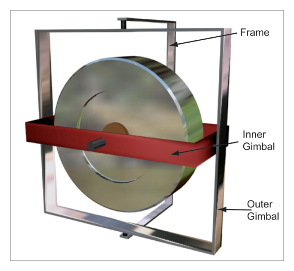
For a gyro to maintain its direction while attached to a manoeuvring aircraft, it needs suspension devices that allow the aircraft to move around it — these are called gimbals.
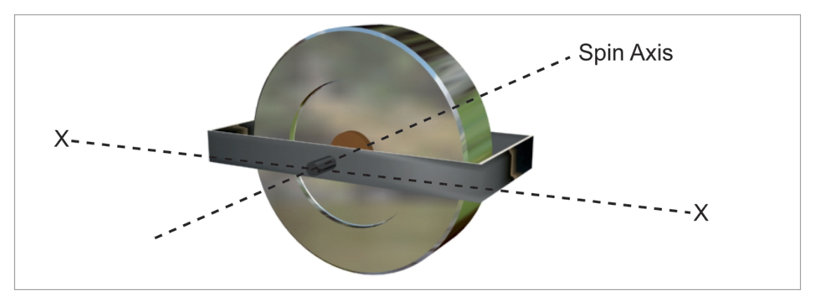
3.1 One Gimbal (One Degree of Freedom)
One gimbal allows the aircraft to bank without disturbing the gyro's spin axis. However, yawing would force the gyro out of its original orientation.
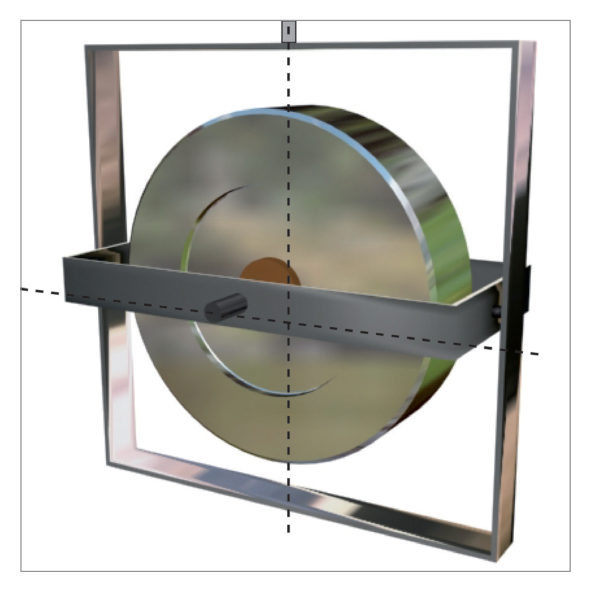
3.2 Two Gimbals (Two Degrees of Freedom)
Two gimbals allow the aircraft to pitch, bank, AND yaw without disturbing the gyro.
4. Precession
Example: If the gyro rotates clockwise (viewed from above) and an upward force is applied at the 12 o'clock position of the spin axis, the effective precession acts at the 3 o'clock position — the rotor moves into the page about the vertical axis.
4.1 Precession in a Gimballed Gyro
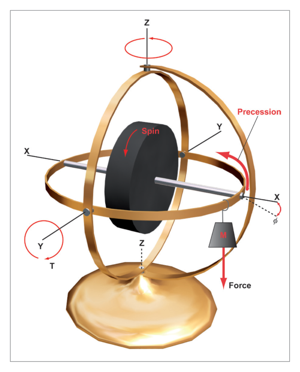
When a small mass M is applied on the inner gimbal (producing a torque about the YY axis):
- The gyro axis tilts through a small angle φ initially.
- The torque is then precessed 90° — the spin axis starts rotating at constant velocity about the ZZ axis.
- If the torque is withdrawn, precession ceases immediately.
- While the torque continues, precession continues at constant velocity.
5. Relationship Between Precession and Rigidity
6. Wander – Drift and Topple
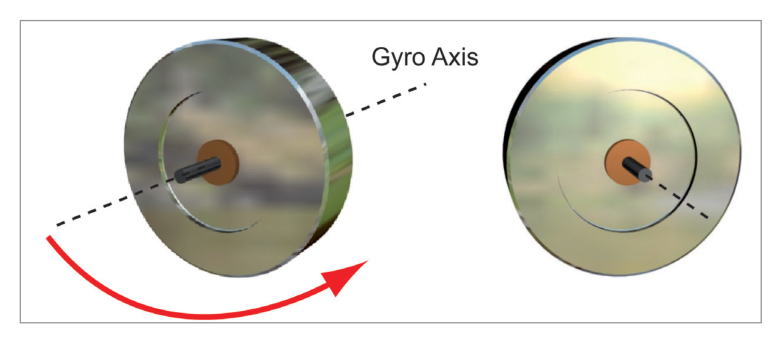
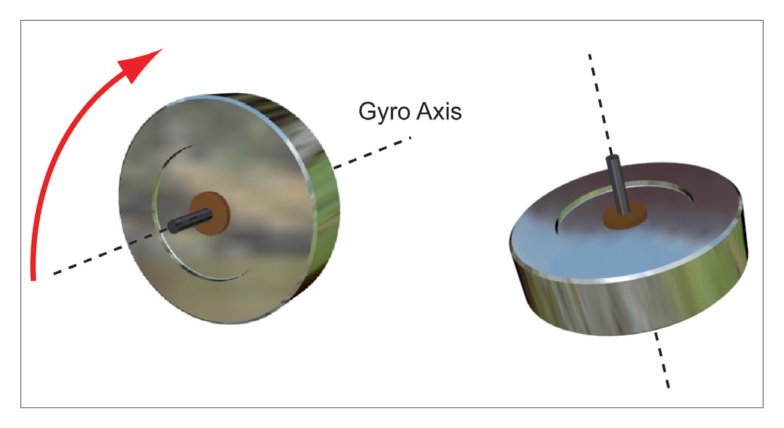
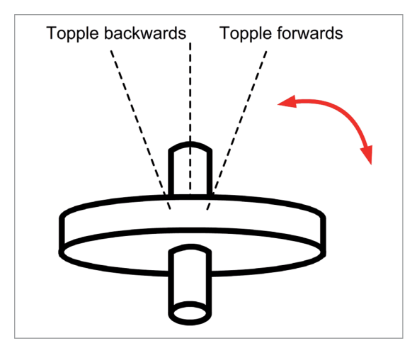
Any departure of a gyro axis from its original orientation is called wander. Wander may be real or apparent, or a combination of both.
| Type of Wander | Plane | Axis Type |
|---|---|---|
| Drift | Horizontal plane | Horizontal axis gyros can drift |
| Topple | Vertical plane | Both horizontal and vertical axis gyros can topple |
7. Real and Apparent Wander
7.1 Real Wander
The gyro axis moves with respect to inertial space. Caused by manufacturing imperfections: uneven rotor bearing friction, gimbal friction, imbalance of rotor mass, unbalanced gimbals. Also called random wander. Can be reduced by higher quality engineering, but at cost.
7.2 Apparent Wander
The gyro remains fixed in inertial space, but the observer's frame of reference changes. Two types:
- Earth Rate — caused by the rotation of the earth
- Transport Wander — caused by flight east or west at latitudes other than the equator
8. Earth Rate
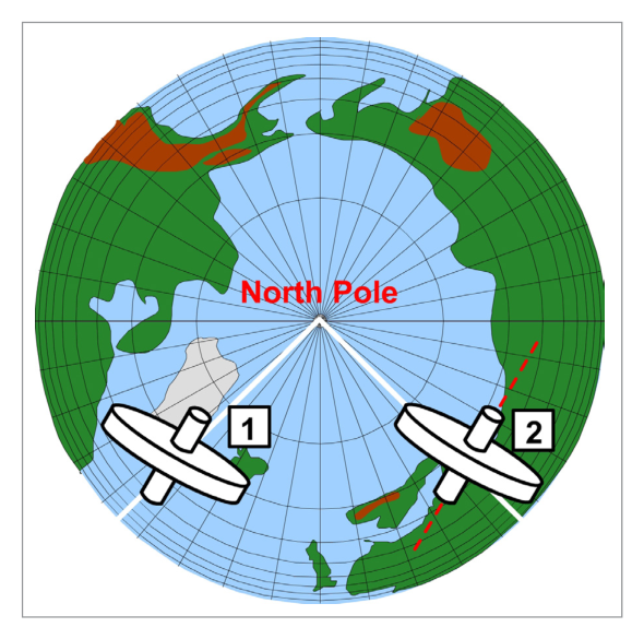
- Northern Hemisphere: Earth rotates anticlockwise when viewed from above N pole → gyro heading appears to decrease → Negative earth rate = −15 × sin(lat) °/hour
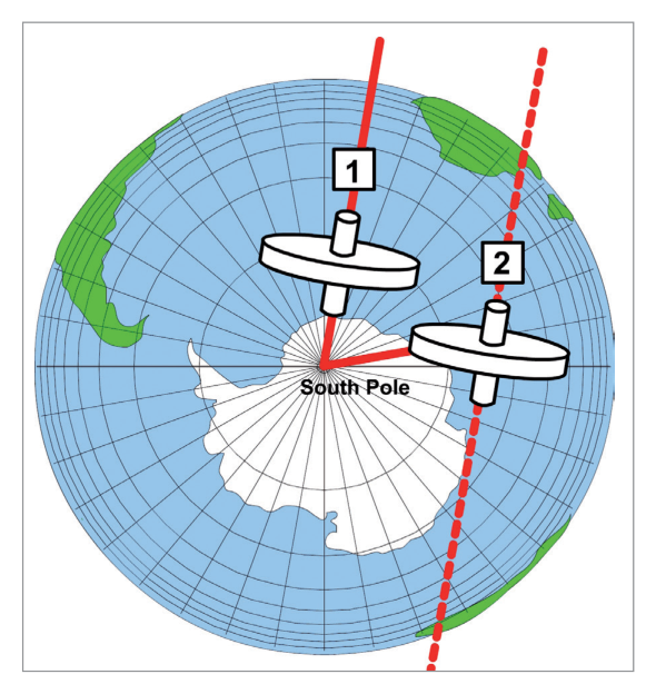
- Southern Hemisphere: Earth rotates clockwise when viewed from above S pole → gyro heading appears to increase → Positive earth rate = +15 × sin(lat) °/hour
9. Transport Wander
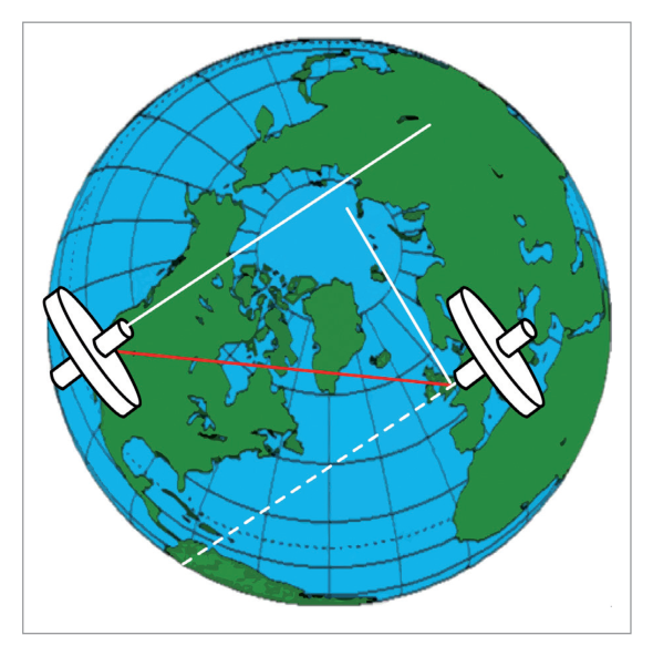
When an aircraft flies east or west, it moves from one meridian to another. The gyro remains fixed in space (aligned with the original meridian), but the local meridian direction (true north) changes as the aircraft's longitude changes. The difference between the gyro's orientation and local true north is transport wander.
Transport wander is equivalent to the difference in meridian alignment between the departure and arrival points — in effect, the convergence of meridians.
10. Types of Gyro – by Function
| Type | Measures | Gimbals | Degrees of Freedom | Examples |
|---|---|---|---|---|
| Displacement Gyro | Angles (e.g. 10° pitch, 5° bank, 30° heading change) | 2 | 2 | DGI, Artificial Horizon |
| Rate Gyro | Angular rate (e.g. 3°/second) | 1 | 1 | Turn Rate Indicator, Yaw Dampers |
10.1 Space Gyros vs. Tied Gyros
| Type | Reference | Wander | Use |
|---|---|---|---|
| Space Gyro | Fixed point in space (distant star) | Free to wander — nothing corrects it back; must have negligible real wander | INS (very expensive, very accurate) |
| Tied Gyro | External reference (magnetic north, gravity) | Corrected back to datum by external force | DGI (slaved to magnetic north), Artificial Horizon (slaved to gravity) |
11. Types of Gyro – by Construction
| Type | Principle | In Service Since | Uses |
|---|---|---|---|
| Tuned Rotor | Traditional spinning disc | Always | Elementary/intermediate training aircraft; basic DGI, AH, Turn Meter |
| Ring Laser Gyro (RLG) | Compares 2 light paths around a glass prism | 1980s | Nearly all modern airliners |
| Fibre Optic Gyro (FOG) | Extension of RLG principle using optical fibre | Recently | Airbus A380 (first commercial aircraft) |
12. Suction vs. Electric Power
12.1 Suction (Air-Driven) Gyros
An engine-driven vacuum pump (or venturi) reduces pressure in the instrument case → filtered air sucked in → air jet directed onto rotor buckets (like a water wheel).
- Moisture, dust, oil, grit in airflow can block the filter → variable rotor RPM
- At high altitude, engine manifold pressure may be insufficient to maintain rotor speed
- Impurities that pass through the filter reduce bearing life and unbalance gimbals
12.2 Electric Gyros
Rotor is part of an electric motor — spun electrically.
- Faster achievement and more accurate maintenance of rotor RPM
- Higher RPM achievable → greater moment of inertia → greater rigidity
- RPM can be more rapidly achieved and more accurately maintained
12.3 Typical Aircraft Gyro Power Arrangement
- Main gyro instruments (DGI, AH): usually electric (for greater accuracy)
- Standby instruments: often air driven (suction) (available after electrical failure)
Both types can suffer power-source failure:
- Electric: A flag indicator alerts the pilot to select standby power.
- Suction: An air pressure (suction) gauge indicates vacuum pump failure. Some have a manually selected alternate power source.
13. Gimbal Lock
Gimbal lock occurs if an aircraft banks to 90°: the inner and outer gimbals take up the same orientation. One degree of freedom is lost. If the pilot then applies pitch input, the gyro is forced out of orientation → violent precession, usually described as toppling.
- Fourth gimbal — adds the extra degree of freedom that prevents lock.
- Gimbal flip mechanism — a torque motor that rapidly flips the outer gimbal by 180° when lock is approaching, restoring freedom.
The chapter concludes by noting that the magnetic compass's susceptibility to turning and acceleration errors could be overcome using a gyroscope as a direction/attitude datum — providing a datum with rigidity in space and immunity to aircraft manoeuvre effects. This leads to the gyro instruments covered in subsequent chapters.
- Simple aircraft: DGI, Artificial Horizon, Turn and Slip Indicator / Turn Co-ordinator
- Complex aircraft: Gyro-magnetic compasses, INS/IRS, Yaw dampers, Autopilots, Radar scanner stabilisation
- Gyro = spinning disc (rotor). Properties: Rigidity + Precession.
- Rigidity ↑ with: mass↑, radius↑ (moment of inertia↑), RPM↑. Mass at rim → max MI for min mass.
- Precession: force precessed 90° in direction of spin. Rate ∝ torque / (MI × RPM).
- Rigidity and precession are inversely related — more of one = less of the other.
- Wander: drift (horizontal plane) or topple (vertical plane). Vertical axis gyros: topple only, no drift.
- Real wander: caused by manufacturing imperfections. Apparent wander: earth rate + transport wander.
- Earth Rate = 15 × sin(lat) °/hour. NH: negative (heading appears to decrease). SH: positive.
- Transport wander: change in meridian alignment during east/west flight.
- Displacement gyro: 2 gimbals, 2 DoF (DGI, AH). Rate gyro: 1 gimbal, 1 DoF (turn indicator).
- Space gyro: fixed in space, free to wander (INS). Tied gyro: corrected to external reference (DGI, AH).
- Construction: Tuned rotor, RLG (1980s, airliners), FOG (A380 first).
- Electric: expensive, heavy, but faster/more accurate RPM. Suction: independent of electrics, but vulnerable to contamination.
- Main gyros: electric. Standby: suction (survives electrical failure).
- Gimbal lock at 90° bank → toppling. Solutions: 4th gimbal or gimbal flip mechanism.
- Gyro rotor: 2–5 cm diameter, 4,000–55,000 rpm.
Practice Questions & Detailed Answers
- (a) "Force applied" is not a determinant of rigidity — it is a determinant of precession rate. Rigidity is a property of the gyro itself, independent of any applied force.
- (b) Rate of precession and force applied relate to the precession equation, not rigidity.
- (c) Rate of precession does not determine rigidity — it is inversely proportional to rigidity.
- (a) The precession rate does change — it is inversely proportional to RPM.
- (b) Increasing RPM increases rigidity and therefore decreases precession — not the other way round.
- (d) Precession would only cease if RPM became infinite, or if the applied torque were removed.
- (a) & (b) Restricting to "real wander only" is incorrect — topple includes apparent wander in the vertical plane.
- (d) Wander in the horizontal plane is drift, not topple.
- (b) Precession direction does not change with hemisphere — it is always 90° in the direction of rotation, a physical law.
- (c) 270° in the direction of spin is the same as 90° in the opposite direction — this would be incorrect.
- (d) The precession rate is inversely proportional to RPM — not directly proportional. And this option describes rate, not direction.
- (b) Earth rotation causes apparent wander (earth rate), not real wander.
- (c) Increasing RPM increases rigidity and does not cause wander — if anything, it reduces precession-induced drift.
- (d) Moving north/south changes transport wander (apparent), not real wander.
- (a) Tied gyro refers to how a gyro is maintained (tied to an external reference), not its number of degrees of freedom.
- (b) Earth gyro refers to the reference datum (local gravity/earth), not degrees of freedom.
- (c) Space gyro refers to the reference (inertial space), not degrees of freedom.
- (a), (b), (d) The space gyro at the equator with axis pointing north has zero horizontal earth rate drift. The gyro does not precess. The axis remains aligned with true north (to a distant star) which does not change direction as seen from the equator in this orientation.
- (a) Electric gyros are heavier and more expensive — not lighter or cheaper — than suction types.
- (b) "Low voltage DC only" is incorrect — electric gyros can use various power supplies. Also, "sealed casing" is not a defining advantage of electric over suction.
- (d) High precession rate would be a disadvantage (means low rigidity). Electric gyros have LOW precession rates (due to high rigidity), not high. Also, they are more expensive, not low cost.
- (b) Clear air turbulence may cause short-term disturbances but is not a source of systematic apparent wander.
- (c) Gimbal friction causes real wander (manufacturing imperfection), not apparent wander.
- (d) External torque causes precession and may cause real wander, but is not apparent wander — apparent wander results from the changing frame of reference, not from a force on the gyro.
Master Reference Tables
| Parameter | Value | Section |
|---|---|---|
| Gyro rotor diameter | 2–5 cm | §1 |
| Gyro rotor speed range | 4,000–55,000 rpm | §1 |
| Earth rotation rate | 15°/hour (360°/24hr) | §8 |
| Earth Rate formula | 15 × sin(latitude) °/hour | §8 |
| Earth rate at equator | 0°/hour (sin 0° = 0) | §8 |
| Earth rate at poles | 15°/hour (sin 90° = 1) | §8 |
| Earth rate sign NH | Negative (heading decreases) | §8 |
| Earth rate sign SH | Positive (heading increases) | §8 |
| Displacement gyro | 2 gimbals, 2 DoF | §10 |
| Rate gyro | 1 gimbal, 1 DoF | §10 |
| Gimbal lock angle | 90° bank | §13 |
| Precession direction | 90° in direction of spin | §4 |
| Vertical axis gyro wander | Topple only (no drift) | §6 |
- Gyro properties: "R.P." → Rigidity and Precession (the two properties)
- Rigidity factors: "Mr. RPM" → Mass, Radius, RPM
- Precession rule: "Force at 12, action at 3" (for clockwise-spinning rotor viewed from above)
- Wander types: "D=Drift=Horizontal. T=Topple=Vertical" (D and H have similar shapes; T is tall like vertical!)
- Earth rate sign: "NH = Negative, SH = Positive" (NH is Northern, Negative)
- Real vs Apparent: "Real = physical defects. Apparent = earth moves around you."
- Gyro types by function: "RATE = 1 (one-gimbal). DISPLACEMENT = 2 (two-gimbal)."
- Space vs Tied: "Space gyro = free to drift (like INS). Tied gyro = leashed to a reference (DGI, AH)."
Answer Key
| Q1 | Q2 | Q3 | Q4 | Q5 | Q6 | Q7 | Q8 | Q9 |
|---|---|---|---|---|---|---|---|---|
| d | c | c | a | a | d | c | c | a |
Reinforce Chapter 11: Gyroscopes
Test your knowledge and practice actual exam questions for Navigation — Instrumentation.