The Turn Co-ordinator
by Ghost Aviator
Table of Contents
1. Introduction and Comparison with TBI
The Turn Co-ordinator is an interesting development of the Turn and Bank Indicator (TBI). It uses the same fundamental principle — a rate gyroscope with a spring restraint — but with two key differences:
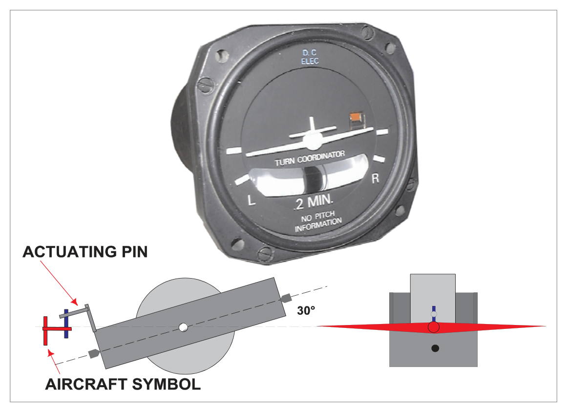
- The precession axis of the rate gyroscope is inclined at approximately 30° with respect to the aircraft's longitudinal axis (in the TBI, the gyro axis is purely horizontal/lateral).
- The display is an aircraft symbol (viewed from behind), rather than a needle, giving a more intuitive roll/turn representation.
2. Gyroscope Axis Orientation — 30° Inclination
In the standard TBI, the rate gyro axis is horizontal — the gyro is sensitive to yaw (turning about the vertical axis) only. In the Turn Co-ordinator, the single gimbal ring is pivoted longitudinally but the gyro axis is tilted at about 30° from the aircraft's longitudinal axis. This inclination gives the gyroscope sensitivity to:
- Banking of the aircraft (roll input) — detected as the aircraft rolls.
- Turning of the aircraft (yaw input) — as in the standard TBI.
The result is that when a turn is initiated by banking, the gyroscope precesses and moves the aircraft symbol to anticipate the resulting turn — even before the yaw rate has fully developed.
flowchart TD
    TBI["Standard TBI\nRate Gyro (horizontal axis)\nSensitive to YAW only\n→ measures rate of turn"]
    TC["Turn Co-ordinator\nRate Gyro (30° inclined)\nSensitive to ROLL + YAW\n→ anticipates turn from bank"]
    TBI -->|"Key Difference"| TC
3. Turn Co-ordinator Operation and Display
When a turn is initiated by banking, the inclined gyroscope precesses and moves the miniature aircraft symbol in the direction of bank, enabling the pilot to anticipate the resulting turn.
The pilot then controls the turn at the required rate by aligning the aircraft symbol with the graduations on the instrument dial. The rate of turn depends on the instrument design — typically Rate 1 (3°/second) is indicated at the standard graduation marks.
4. Important Annotation — No Pitch Information
5. Comparison: Turn Co-ordinator vs Turn and Slip Indicator
| Feature | Turn and Slip Indicator (TBI) | Turn Co-ordinator (TC) |
|---|---|---|
| Gyro type | Rate gyro | Rate gyro |
| Number of gimbals | 1 | 1 |
| Gimbal pivot axis | Lateral (horizontal) | Longitudinal |
| Gyro axis inclination | Purely horizontal | ≈30° to longitudinal axis |
| Sensitive to | Yaw only | Roll AND Yaw |
| Turn anticipation | No — indicates only after yaw develops | Yes — responds to initial bank |
| Display type | Needle pointer | Aircraft symbol (miniature aircraft) |
| Slip indicator | Ball in curved tube | Ball in curved tube (same) |
| Pitch information | None | None ("No Pitch Information") |
| Can topple? | No (only 1 gimbal) | No (only 1 gimbal) |
- Turn Co-ordinator = development of TBI with inclined gyro axis at ≈30° to the longitudinal axis.
- Single gimbal ring pivoted longitudinally (vs. TBI which pivots laterally).
- Sensitive to both roll and yaw — anticipates turn from initial bank.
- Display: miniature aircraft symbol, not a needle.
- Ball (slip indicator) functions identically to the TBI — central = balanced turn.
- "No Pitch Information" annotation is mandatory — the aircraft symbol gives no pitch data.
- Like the TBI, the Turn Co-ordinator has only one gimbal — it cannot topple.
- Rate 1 = 3°/second; standard graduation = Rate 1 alignment mark.
Practice Questions & Detailed Answers
- (a) — The 30° inclination does not improve rate of turn accuracy; it adds sensitivity to roll.
- (c) — The inclination has nothing to do with inverted flight.
- (d) — The rotor speed is determined by the power supply, not the gimbal inclination angle.
- (a) — 180° in 2 minutes = 1.5°/second, which is less than Rate 1 (3°/sec). While numerically possible for a very slow turn, this option incorrectly implies it is on the Rate 1 mark.
- (b) — 90° in 1 minute = 1.5°/sec, again less than Rate 1. However, the question asks what the indication specifically means, not a calculation. If the symbol is between centre and the Rate 1 mark, it is less than Rate 1 by definition.
- (d) — Rate 1 (3°/sec) would be indicated by the symbol exactly on the Rate 1 graduation, not between marks.
- (a) and (d) — "Two gimbal rings" is incorrect. Two rings would give two degrees of freedom (like a DGI or AH). The rate gyro instruments have only one gimbal.
- (c) — "Laterally" describes the TBI, not the Turn Co-ordinator. The TC gimbal is pivoted longitudinally.
Master Reference Tables
| Parameter | Value | Section |
|---|---|---|
| Gyro axis inclination | ≈30° to longitudinal axis | 2 |
| Number of gimbals | 1 (single) | 2 |
| Gimbal pivot direction | Longitudinal | 2 |
| Rate 1 (standard graduation) | 3°/second | 3 |
| Sensitive to | Roll AND Yaw | 2 |
| Can topple? | No | 2 |
| Pitch information? | No — "No Pitch Information" | 4 |
Answer Key Summary
| Q | Answer | Key Topic |
|---|---|---|
| 1 | b | 30° inclination → sensitive to roll AND yaw |
| 2 | c | Symbol between centre and Rate 1 mark = less than 3°/sec |
| 3 | b | Single gimbal ring, pivoted longitudinally |
Reinforce Chapter 15: The Turn Co-ordinator
Test your knowledge and practice actual exam questions for Navigation — Instrumentation.