Electrical Fundamentals
by Ghost Aviator
Part II (i) Electrical units — volt, ampere, ohm, watt; wavelength, frequency & their relationship
Learning objectives — by the end of this chapter you will be able to…
- Define voltage, current, resistance and power with their units and symbols.
- Apply Ohm's Law and the power formulae, and solve numerical problems.
- Distinguish AC from DC, and explain RMS, peak, frequency and period.
- State the factors affecting resistance and combine resistors in series and parallel.
- Explain capacitance, inductance and reactance, and why they matter for tuning.
- Relate frequency, wavelength and the speed of radio waves and convert units.
7.1 The four quantities
7.2 Ohm's Law
7.3 Power
7.4 AC & DC
7.5 Resistance & materials
7.6 Series & parallel circuits
7.7 Capacitance, inductance & reactance
7.8 Frequency, period & wavelength
7.1 The four quantities
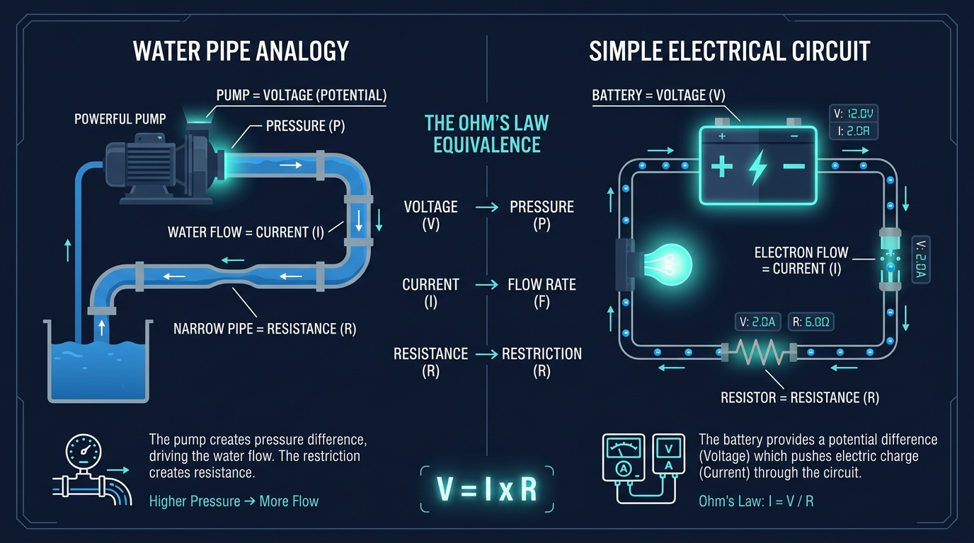
Picture electricity as water in a pipe. Voltage is the pressure pushing the water; current is how much water flows per second; resistance is how narrow the pipe is; power is the useful work the flow does. The analogy is exact enough to carry you through every formula in this chapter.
| Quantity | Symbol | Unit | Precise meaning |
|---|---|---|---|
| Voltage (EMF / p.d.) | V (or E) | Volt (V) | Energy given to / taken from each coulomb of charge — the "push" |
| Current | I | Ampere (A) | Rate of flow of charge: 1 A = 1 coulomb per second |
| Resistance | R | Ohm (Ω) | Opposition to current flow |
| Power | P | Watt (W) | Rate of doing work / using energy: 1 W = 1 joule per second |
EMF (electromotive force) is the voltage a source produces (e.g. a battery's 12 V). Potential difference (p.d.) is the voltage across a component in the circuit. They differ by the voltage lost across the source's own internal resistance when current flows.
7.2 Ohm's Law
Push harder (more volts) and more current flows; narrow the pipe (more ohms) and less flows. The three lock together:
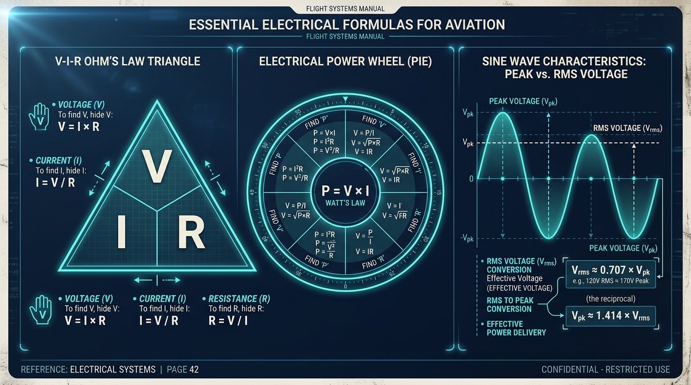
Draw a triangle: V on top, I and R below. Cover the one you want: cover V → I × R; cover I → V/R; cover R → V/I. "Very Important Rule."
A 28 V aircraft bus supplies a 14 Ω heater. Current = V/R = 28 ÷ 14 = 2 A.
If the resistance halves to 7 Ω, current doubles to 4 A (inverse relationship). If the bus sags to 24 V across the original 14 Ω, current = 24 ÷ 14 ≈ 1.71 A.
7.3 Power
From 7.2: 28 V across 14 Ω drawing 2 A. P = V × I = 28 × 2 = 56 W.
Check with I²R = 2² × 14 = 4 × 14 = 56 W. Check with V²/R = 28² ÷ 14 = 784 ÷ 14 = 56 W. All agree.
1 kW = 1000 W. Efficiency = useful output power ÷ input power (always < 100% because some energy becomes heat). A transmitter rated 50 W output draws more than 50 W from the bus because the power amplifier is not perfectly efficient.
7.4 AC & DC
DC (Direct Current) flows in one direction at a steady value — e.g. a battery.
AC (Alternating Current) reverses direction periodically, tracing a sine wave; the number of complete cycles per second is the frequency (hertz), and the time for one cycle is the period (T = 1/f). Every radio-frequency signal is alternating current.
An AC wave is described by its peak value, its peak-to-peak (twice peak), and its RMS (root-mean-square) — the equivalent DC value that would do the same heating work. For a sine wave: RMS = 0.707 × peak (and peak = 1.414 × RMS). Mains and aircraft AC voltages are quoted as RMS.
A typical aircraft has a 28 V DC system (battery/bus feeding avionics) and a 115 V AC at 400 Hz system (for many instruments and as the form every radio signal takes on the way to the antenna). 400 Hz is used rather than 50/60 Hz because transformers and motors can be smaller and lighter at the higher frequency — a real weight saving.
7.5 Resistance & materials
| Material type | Behaviour | Example |
|---|---|---|
| Conductor | Many free electrons — low resistance | Copper, aluminium, silver |
| Insulator | Almost no free electrons — very high resistance | PVC, rubber, glass, air |
| Semiconductor | In between; conductivity controllable — the basis of all radio electronics | Silicon, germanium (diodes, transistors) |
Resistance increases with length, decreases with cross-sectional area (a thicker wire conducts better), depends on the material (its resistivity), and — for most metals — increases with temperature. Hence a long, thin, hot wire has the highest resistance.
7.6 Series & parallel circuits
| Series | Parallel | |
|---|---|---|
| Path | One single loop | Multiple branches |
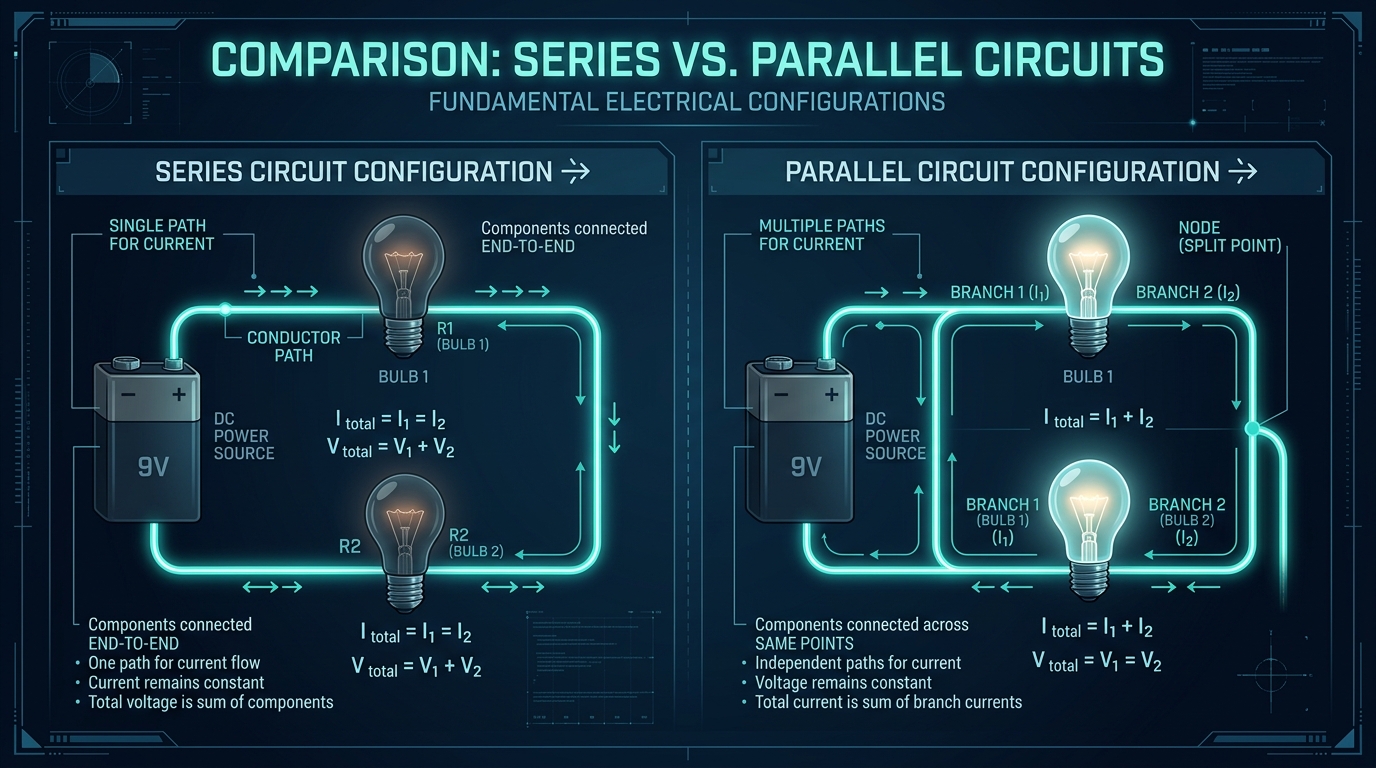
| Current | Same through every component | Splits between branches |
| Voltage | Divides across components | Same across each branch |
| Total resistance | R = R+ + R&sub2; + ... (adds up) | 1/R = 1/R+ + 1/R&sub2; + ... (less than the smallest) |
| If one opens | Whole circuit stops | Other branches keep working |
Series: 10 Ω + 20 Ω = 30 Ω. Across 30 V the current = 30/30 = 1 A; the 10 Ω drops 10 V and the 20 Ω drops 20 V (voltage divides).
Parallel: two 10 Ω resistors → 1/R = 1/10 + 1/10 = 2/10, so R = 5 Ω (half of one). For two equal resistors, parallel total = half the value; the current splits equally.
Series = Same current; Parallel = same Pressure (voltage). Resistances add in series and reduce in parallel.
7.7 Capacitance, inductance & reactance
Resistors oppose current the same at any frequency. Capacitors and inductors oppose AC by an amount that depends on frequency — and that frequency dependence is exactly what lets a radio tune to one station and reject the rest.
Capacitor — stores energy in an electric field; blocks DC, passes AC more easily as frequency rises (its reactance falls with frequency). Unit: farad (F).
Inductor — stores energy in a magnetic field; passes DC, opposes AC more as frequency rises (its reactance rises with frequency). Unit: henry (H).
Their frequency-dependent opposition is called reactance (X), measured in ohms.
Put an inductor and capacitor together and at one special resonant frequency their reactances cancel, giving a sharp peak in response. A tuned LC circuit selects that frequency and rejects others — this is how a receiver is "tuned" to a station and how a transmitter sets its operating frequency.
7.8 Frequency, period & wavelength
Every radio wave travels at the speed of light. Its frequency (cycles per second) and its wavelength (length of one cycle) are two views of the same wave — fix the speed and one decides the other.
1 kHz = 1,000 Hz · 1 MHz = 1,000,000 Hz · 1 GHz = 1,000 MHz. Period and frequency are reciprocals: a 1 MHz signal has a period of 1 microsecond.
A 120 MHz VHF signal: λ = c/f = (3 × 10&sup8;) ÷ (120 × 10&sup6;) = 2.5 m.
A 300 MHz signal: λ = (3 × 10&sup8;) ÷ (300 × 10&sup6;) = 1 m. A 3 MHz HF signal: λ = (3 × 10&sup8;) ÷ (3 × 10&sup6;) = 100 m. Higher frequency → shorter wavelength.
Frequency and wavelength are inversely proportional: as frequency goes up, wavelength comes down. Mixing this round is the classic error, and it explains why high-frequency aerials are short and low-frequency aerials are long.
☆ Numbers to memorise
| Fact | Value |
|---|---|
| Units | Volt (V) · Ampere (A) · Ohm (Ω) · Watt (W) · Farad (F) · Henry (H) |
| Ohm's Law | V = I × R |
| Power | P = V × I = I²R = V²/R |
| RMS (sine) | RMS = 0.707 × peak · peak = 1.414 × RMS |
| Aircraft power | 28 V DC · 115 V AC 400 Hz |
| Series / parallel | Series: R adds, same current · Parallel: R reduces, same voltage |
| Reactance | Capacitor falls with f · Inductor rises with f · LC resonance = tuning |
| Wave relationship | c = f × λ · c = 3 × 10&sup8; m/s · f = 1/T |
Part A — MCQs (click an option to check)
Part B — Oral / viva (tap to reveal model answers)
Part C — Numerical problems (tap for worked solutions)
60-SECOND REVISION CARD
- Volt · Ampere · Ohm · Watt — pressure, flow, opposition, work. V = I × R, P = VI = I²R = V²/R.
- AC reverses (sine); RMS = 0.707 × peak. Aircraft: 28 V DC / 115 V 400 Hz AC.
- Resistance: ↑ length/temperature, ↓ area. Series adds R (same current); parallel reduces R (same voltage).
- Capacitor reactance ↓ with f; inductor reactance ↑ with f; LC resonance = tuning.
- c = f × λ, c = 3 × 10&sup8; m/s; higher f → shorter λ; f = 1/T.
Reinforce Chapter 7: Electrical Fundamentals
Test your knowledge and practice actual exam questions for Radio Telephony.