17
RADIO NAV — CHAPTER 17 · NOTES
EFIS
by Ghost Aviator
Ghost Aviator
www.ghostaviator.com
Ghost Aviator
www.ghostaviator.com
Ghost Aviator
DGCA CPL / ATPL Study Notes • Radio Navigation • Ch 17
✈ Chapter 17: EFIS
Electronic Flight Information System
📋 Contents
1. Introduction 2. EFIS Components 3. EHSI Controller 4. Display Modes 5. EHSI Colour Coding 6. EHSI Symbology 7. Interpreting Displays 8. EFIS Summary 9. Practice Questions (9 Q)1. Introduction
The Electronic Flight Information System (EFIS) replaces conventional electromechanical flight instruments with colour electronic displays. The EHSI (Electronic Horizontal Situation Indicator) displays navigation, radar and TCAS information in multiple selectable modes. EASA AMJ CS-25 governs colour coding and display requirements.
Fig 17.1: EFIS overview — EADI/PFD (left) and EHSI/ND (right) with symbol generator inputs
📡 EHSI Inputs
- VOR (frequency, radial, deviation)
- DME (distance, groundspeed)
- ILS (localizer and glideslope deviation)
- ADF (relative bearing)
- FMS/FMC (waypoints, track, flight plan route)
- AWR (weather radar overlay)
- TCAS (traffic advisories)
2. EFIS Components
Fig: EFIS architecture — dual symbol generators feeding port and starboard EHSI and EADI displays
📡 EFIS System Architecture
| Component | Function |
|---|---|
| EADI / PFD | Electronic Attitude Director Indicator / Primary Flight Display — attitude, airspeed, altitude, VSI, ILS deviations |
| EHSI / ND | Electronic HSI / Navigation Display — heading, track, bearing pointers, waypoints, weather |
| Symbol Generator | Processes all sensor inputs into display symbols for EHSI and EADI |
| EFIS Controller | Pilot interface — mode selection, range, data overlays (WXR, VOR, ARPT etc.) |
| EICAS/ECAM | Engine/systems monitoring display (Boeing/Airbus respectively) |
3. EHSI Controller
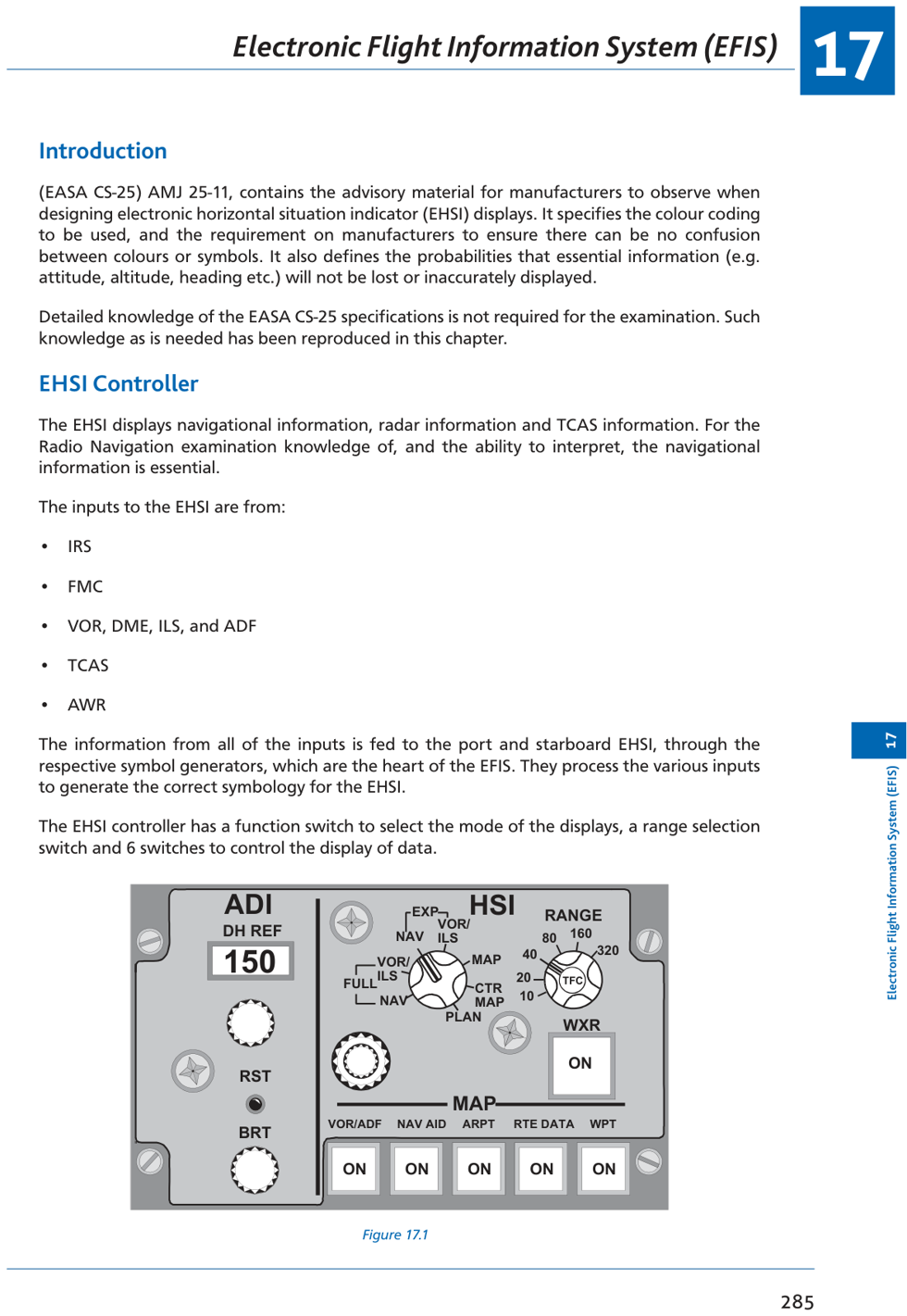
Fig: EFIS controller panel — mode selector, range knob, overlay switches (WXR, VOR, ARPT, WPT, etc.)
📡 EHSI Controller Functions
| Control | Options / Effect |
|---|---|
| Mode Selector | ILS, VOR, MAP, PLAN (selects display format) |
| Range Selector | Selects scale of display (10, 20, 40, 80, 160, 320 NM) |
| WXR switch | Enables weather radar overlay (Expanded VOR/ILS and MAP modes only) |
| STA/VOR | Display tuned VOR/ADF radials |
| NAV AID | Display navigation aids (VOR, NDB symbols) from database |
| ARPT | Display airports from database |
| WPT | Display waypoints on MAP mode |
| RTE DATA | Display route data (ETAs, fuel predictions) at waypoints |
| TCAS switch | Toggle TCAS traffic display on/off; press to clear TCAS FAIL message |
4. Display Modes
EHSI mode options — Full Rose VOR, Expanded VOR, Full Rose ILS, Expanded ILS, MAP, PLAN
📡 EHSI Display Modes
| Mode | Description | WXR/TCAS | Orientation |
|---|---|---|---|
| Full Rose VOR | 360° compass rose; VOR course/deviation; two bearing pointers | ✗ | Heading-up |
| Expanded VOR | Arc display (~120° arc); VOR course, DME, deviation bar; range arcs shown | ✓ | Heading-up |
| Full Rose ILS | 360° rose; ILS course/localizer deviation; glideslope on EADI | ✗ | Heading-up |
| Expanded ILS | Arc display; ILS/LOC course deviation; range arcs shown | ✓ | Heading-up |
| MAP | Moving map centered on aircraft; waypoints, airports, route, weather | ✓ | Heading-up |
| PLAN | Static map of flight plan; waypoints, airports, NAVAIDs; NOT heading-up | ✗ | True North-up |
⚠ Key Points
- WXR and TCAS: only displayable in Expanded VOR/ILS and MAP modes
- PLAN mode is North-up; all others are Heading-up (magnetic or true)
- Range arcs (white): displayed in expanded modes when WXR on, and MAP at all times
- MAP mode selectable overlays: VOR/ADF, NAV AID, ARPT, RTE DATA, WPT, WXR, TCAS
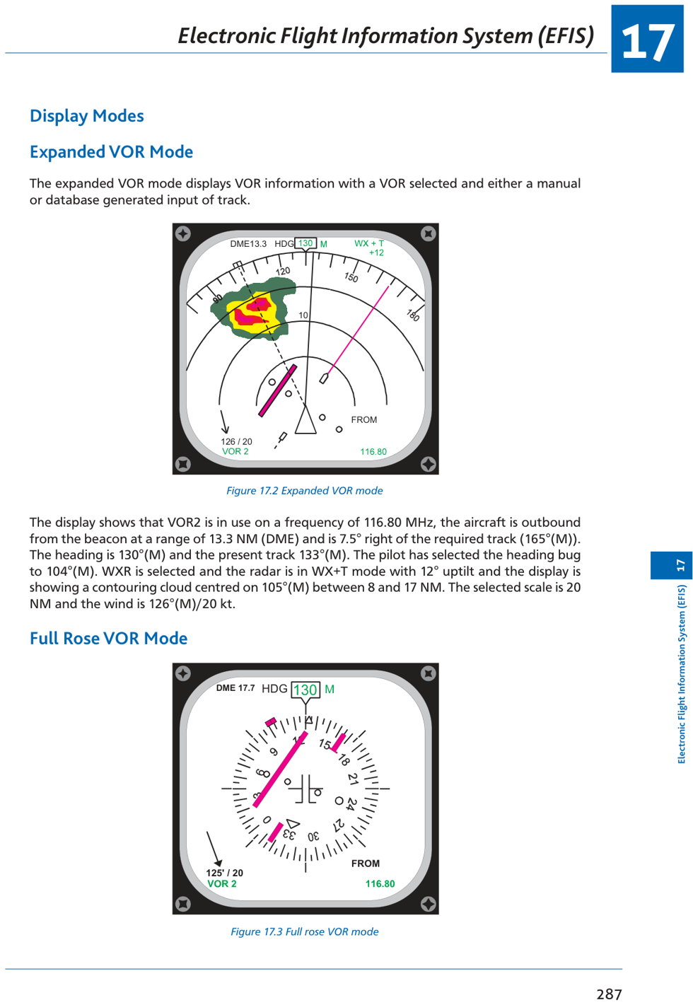
Fig 17.2: Expanded VOR mode — aircraft position relative to VOR, DME distance, heading, track, wind
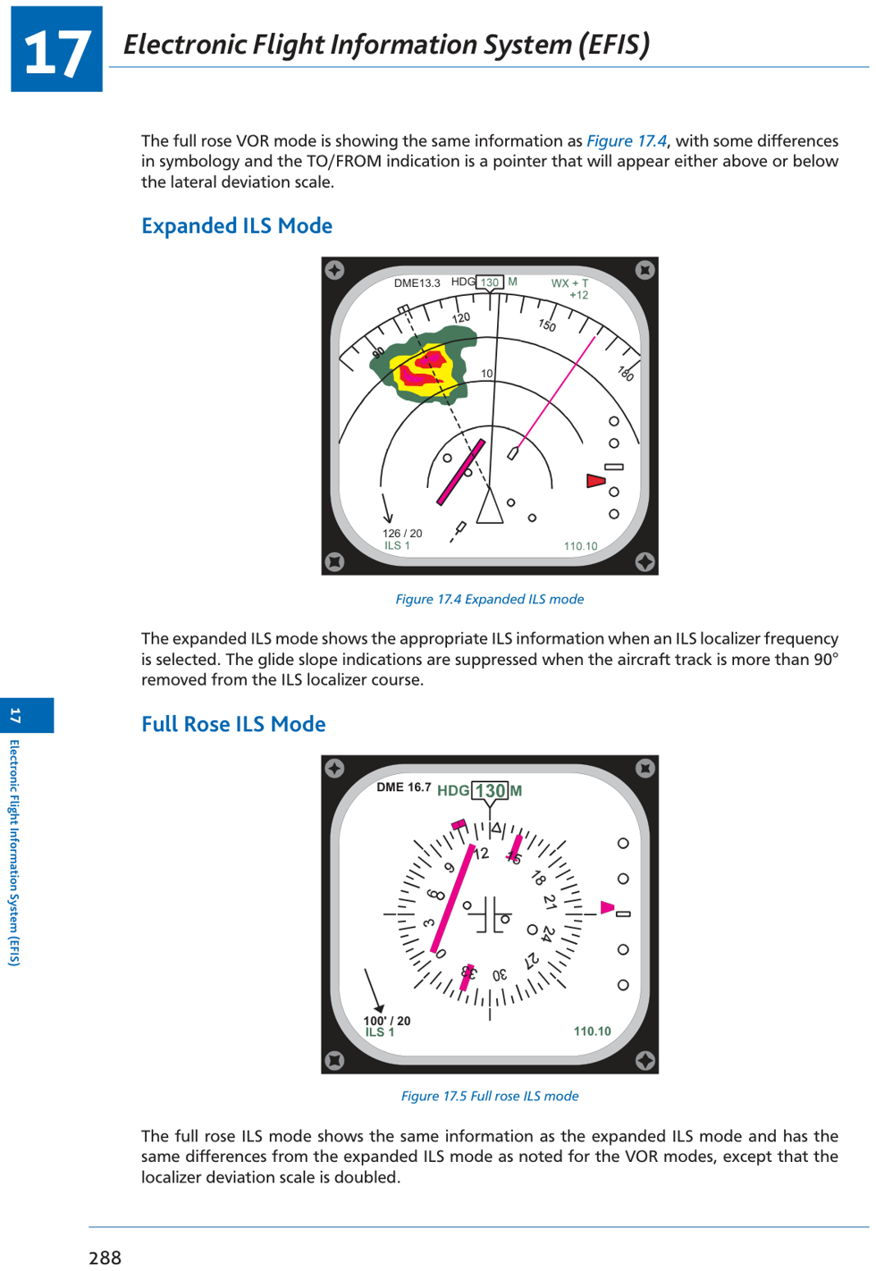
Fig 17.3: Full Rose VOR mode — bearing pointers, VOR1/VOR2 select, CDI deviation
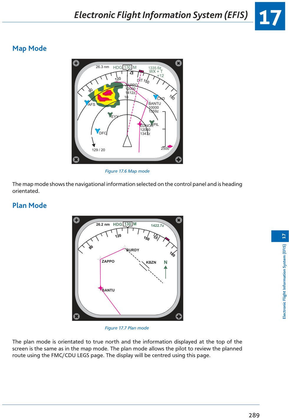
Fig: Expanded ILS mode — LOC deviation bar, range arcs, weather overlay, heading bug
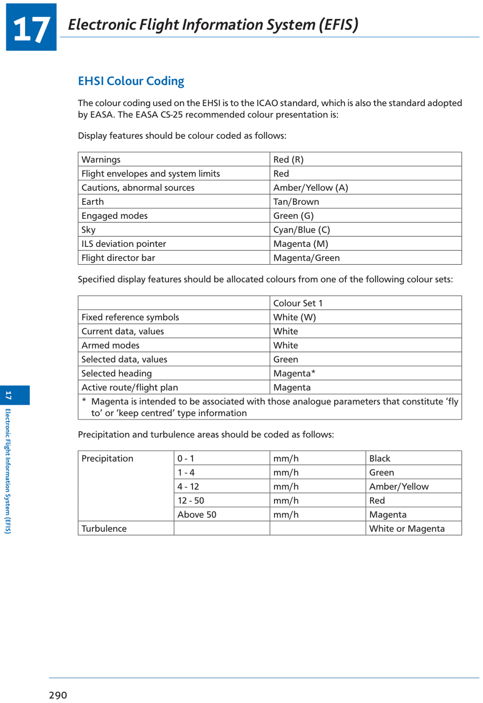
Fig: MAP mode — waypoints, airways, airports overlaid on moving map with range rings
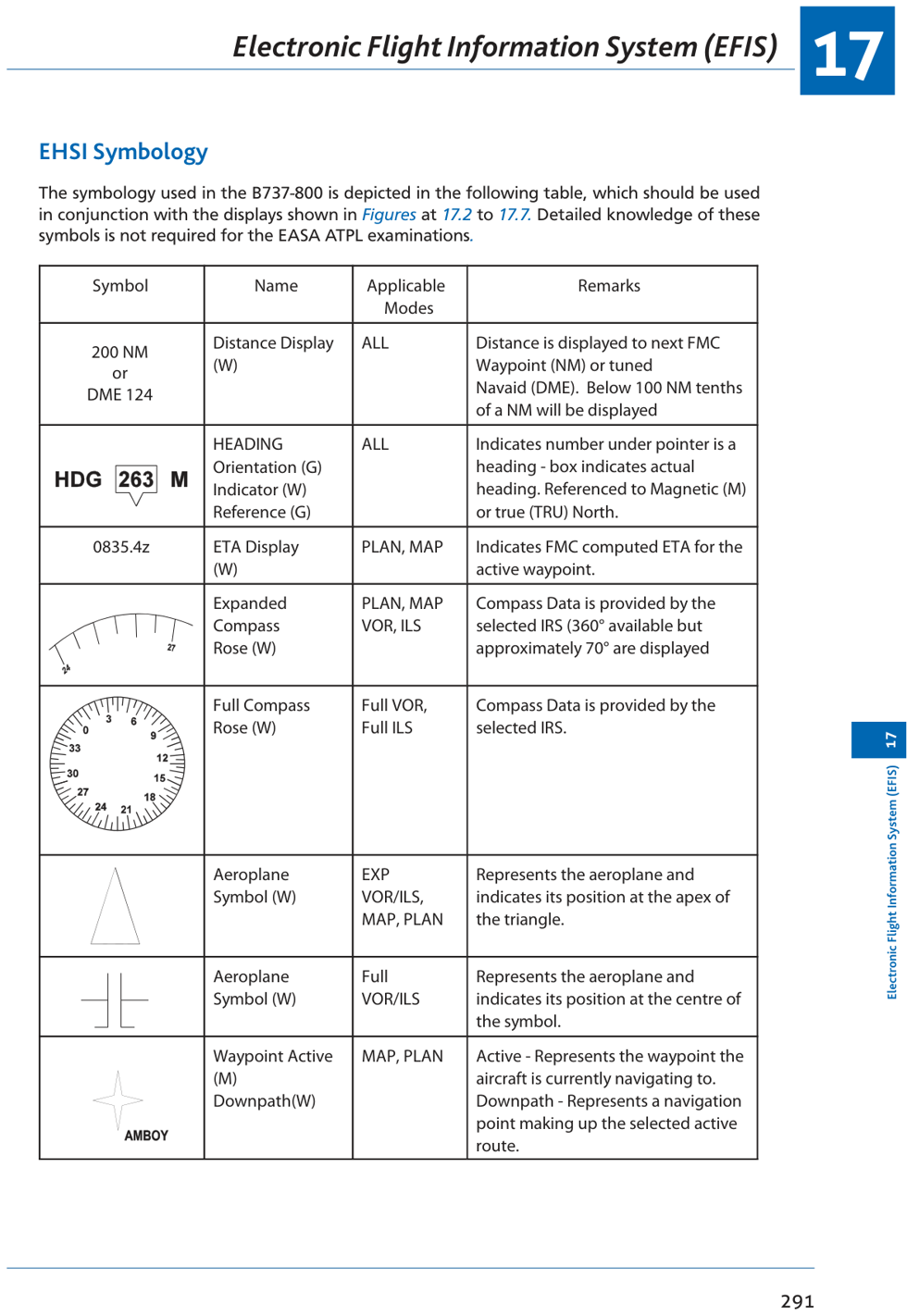
Fig: PLAN mode — north-up static flight plan display; aircraft position shown as symbol
5. EHSI Colour Coding (EASA CS-25)
📡 Standard EHSI Colours
| Colour | Used For |
|---|---|
| YELLOW/AMBER | Caution/advisory; items requiring attention but not immediate action |
| RED | Warnings; immediate action required; flight envelope exceedances |
| GREEN | Normal operation; active armed mode annunciation; on-course deviation |
| WHITE | Present values, scales, range arcs, heading information |
| CYAN/BLUE | Sky on EADI; engaged modes; selected altitude above present |
| MAGENTA | Active flight plan path; FMS/LNAV command bars; active waypoints |
⚠ Colour Rules (CS-25)
- RED used only for warnings — never for advisory or normal information
- AMBER/YELLOW for cautions and non-normal conditions only
- System must ensure no confusion between colours or symbols is possible
- Critical information (attitude, altitude, heading) must not be lost or inaccurately displayed
6. EHSI Symbology
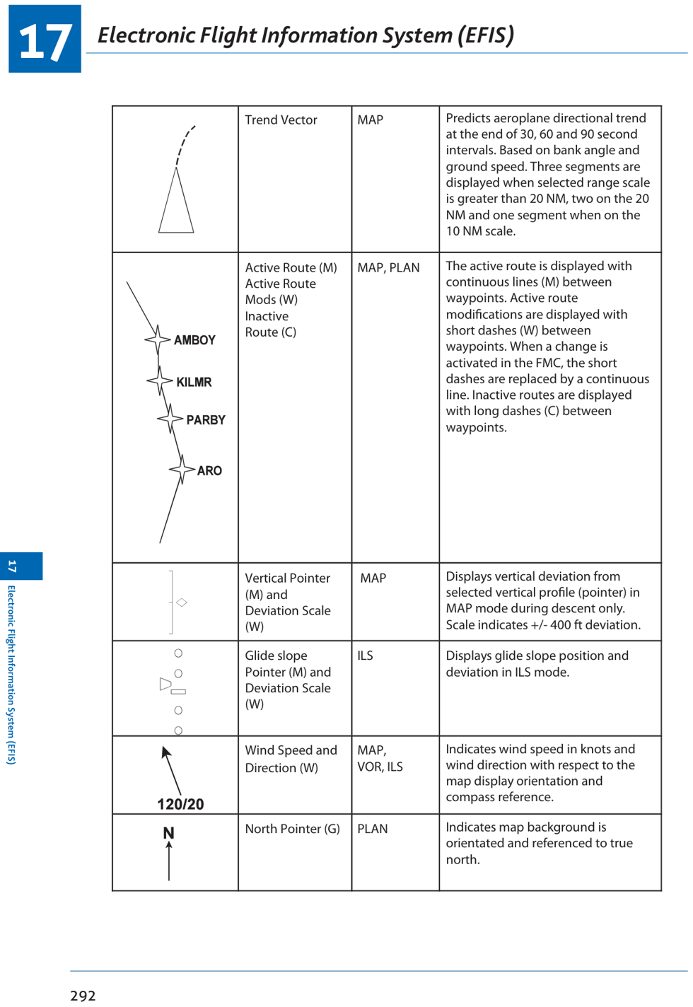
EHSI symbology guide — aircraft symbol, bearing pointers, range arcs, course bar, TCAS intruders
📡 Key EHSI Symbols
| Symbol | Meaning |
|---|---|
| ⇧ (aircraft symbol) | Own aircraft position; heading shown by nose direction |
| Course deviation bar | Lateral deviation from selected course (1 dot = typically 2° VOR or 0.5° LOC) |
| VOR1 bearing pointer (single) | Bearing to selected VOR1 |
| VOR2/ADF pointer (double) | Bearing to VOR2 or ADF |
| Heading bug (cyan) | Selected heading (MCP/FCU heading select) |
| Wind arrow & velocity | Current wind direction and speed |
| Range arc (white) | Distance markers from aircraft; scale-dependent |
| TCAS traffic (cyan/amber/red) | Intruder aircraft; proximity advisory (cyan), traffic advisory (amber), resolution advisory (red) |
7. Interpreting EHSI Displays
✓ Reading an Expanded VOR Display (Typical Exam Q)
Example: VOR2 selected, 116.80 MHz. Aircraft outbound from beacon, 13.3 NM (DME). 7.5° right of required track 165°(M). Heading 130°(M), track 133°(M). Heading bug 104°(M). WXR on WX+T mode, 12° uptilt, cloud 105°(M) at 8–17 NM. Scale 20 NM. Wind 126°(M)/20 kt.
- Course deviation bar is 7.5° to the LEFT of aircraft symbol → aircraft is 7.5° RIGHT of track
- Bearing pointer points behind aircraft (outbound from VOR)
- Weather contour centred at 105°(M) — shown as coloured return from radar
8. EFIS Summary
| Parameter | Detail |
|---|---|
| EHSI inputs | VOR, DME, ILS, ADF, FMS, AWR, TCAS |
| Processor | Symbol generators (port and starboard) |
| Display modes | Full Rose VOR/ILS, Expanded VOR/ILS, MAP, PLAN |
| WXR/TCAS display | Expanded VOR/ILS and MAP modes only |
| PLAN mode orientation | North-up (true); all others: heading-up |
| Active route | Magenta |
| Warnings | Red only |
| Cautions | Amber/yellow |
| Normal/scales | White |
| Active modes | Green |
| FMS commands | Magenta |
| Standard | EASA CS-25 AMJ 25-11 |
9. Practice Questions
Q1. The orientation of the PLAN mode of an EHSI display is:
(a) magnetic north-up
(b) track-up
(c) true north-up
(d) heading-up
Answer: (c)
PLAN mode is oriented to true north-up. All other EHSI modes (VOR, ILS, MAP) are heading-up.
PLAN mode is oriented to true north-up. All other EHSI modes (VOR, ILS, MAP) are heading-up.
Q2. Weather radar information can only be displayed in:
(a) MAP mode only
(b) expanded VOR/ILS and MAP modes
(c) all modes
(d) full rose and MAP modes
Answer: (b)
WXR (weather) and TCAS can only be displayed in Expanded VOR/ILS and MAP modes.
WXR (weather) and TCAS can only be displayed in Expanded VOR/ILS and MAP modes.
Q3. The colour used for the active FMS flight plan path on an EHSI is:
(a) green
(b) white
(c) magenta
(d) cyan
Answer: (c)
The active FMS flight plan path is shown in magenta. Green = normal/active modes. White = scales/present values. Cyan = sky/selected altitude/heading bug.
The active FMS flight plan path is shown in magenta. Green = normal/active modes. White = scales/present values. Cyan = sky/selected altitude/heading bug.
Q4. The EHSI symbol generator receives inputs from:
(a) VOR, ILS, DME only
(b) VOR, ILS, DME, ADF, FMS, AWR, TCAS
(c) FMS only
(d) ILS and VOR only
Answer: (b)
Symbol generators process inputs from: VOR, DME, ILS, ADF, FMS, AWR, and TCAS.
Symbol generators process inputs from: VOR, DME, ILS, ADF, FMS, AWR, and TCAS.
Q5. According to EASA CS-25, which colour is used exclusively for warnings:
(a) amber
(b) green
(c) white
(d) red
Answer: (d)
Red is used exclusively for warnings requiring immediate action. Amber/yellow for cautions. Green for normal operations. White for scales.
Red is used exclusively for warnings requiring immediate action. Amber/yellow for cautions. Green for normal operations. White for scales.
Q6. Range arcs on the EHSI are displayed in:
(a) MAP mode only
(b) all modes at all times
(c) expanded VOR/ILS when WXR selected, and MAP mode always
(d) full rose modes only
Answer: (c)
Range arcs (white) displayed in expanded VOR and ILS modes when WXR is ON, and in MAP mode at all times.
Range arcs (white) displayed in expanded VOR and ILS modes when WXR is ON, and in MAP mode at all times.
Q7. On the EHSI Expanded VOR display, the aircraft is shown 7.5° to the right of track 165°. The course deviation bar will appear:
(a) 7.5° to the left of the aircraft symbol
(b) 7.5° to the right
(c) directly ahead
(d) behind the aircraft
Answer: (a)
If the aircraft is to the RIGHT of track, the course bar (track) is displaced to the LEFT of the aircraft symbol — same as a CDI where the needle deflects toward the selected course.
If the aircraft is to the RIGHT of track, the course bar (track) is displaced to the LEFT of the aircraft symbol — same as a CDI where the needle deflects toward the selected course.
Q8. The TCAS switch on the EHSI controller, when pressed with TCAS already displayed:
(a) increases TCAS range
(b) removes TCAS from display
(c) changes TCAS mode
(d) has no effect
Answer: (c)
Pressing TCAS when displayed removes TCAS information. When TCAS FAIL is displayed, pressing it removes the message.
Pressing TCAS when displayed removes TCAS information. When TCAS FAIL is displayed, pressing it removes the message.
Q9. Selectable overlays available in MAP mode include:
(a) VOR/ADF, airports, waypoints, weather
(b) ILS only
(c) weather only
(d) waypoints and ILS only
Answer: (c)
In MAP mode, the selectable overlays are: VOR/ADF radials, NAVAIDs, airports, waypoints, route data, weather (WXR), and TCAS.
In MAP mode, the selectable overlays are: VOR/ADF radials, NAVAIDs, airports, waypoints, route data, weather (WXR), and TCAS.
DGCA CPL/ATPL Radio Navigation Study Notes
Chapter 17 — EFIS (Electronic Flight Information System)
Ghost Aviator | www.ghostaviator.com
For personal study use only.
Chapter 17 — EFIS (Electronic Flight Information System)
Ghost Aviator | www.ghostaviator.com
For personal study use only.
Study Radio Nav with other student pilots
Join the free Radio Nav group on Telegram. Stuck on a doubt? Type /q and your question, and get an answer from Ghost Aviator's notes.
LIVE BATCH
Study Radio Navigation live with the Captain
Small batch of 10 · live doubt-clearing · 4–6 weeks · ₹12,999 ₹7,999
Reinforce Chapter 17: EFIS
Test your knowledge and practice actual exam questions for Radio Navigation.
Planning your Pilot Training in 2026?
Calculate exact flying hours, DGCA exam fees, and living costs with our interactive calculator.