Aerodynamic Warnings
by Ghost Aviator
Table of Contents
1. Introduction
2. Altitude Alerting System
Height Bands
| Aircraft | Approach Band | Deviation Band |
|---|---|---|
| Boeing | 300–900 ft of selected altitude | 300 ft from selected altitude |
| Airbus | 250–750 ft of selected altitude | — |
Boeing 747-400 Operation
Approaching selected altitude:
- At 900 ft prior: white box around current altitude on PFD + momentary aural alert
- At 300 ft prior: white box disappears
Deviation from selected altitude: At 300 ft from selected:
- Master caution lights illuminate
- Continuous caution beeper sounds
- EICAS caution message ALTITUDE ALERT displayed
- Current altitude box changes to amber
- Glide slope is captured, OR
- Landing flaps are selected with the gear down
Regulatory Requirement
EASA CAT aircraft must have altitude alerting if:
- Turboprop > 5700 kg or > 9 passenger seats, or
- Any turbojet aircraft
3. Overspeed Warning
Operation
When overspeed occurs (EFIS aircraft):
- Sounds the siren or horn
- Illuminates red master WARNING lights
- Displays OVERSPEED on EICAS upper display in red
Input: ADC via FWS. Can be tested on ground by pressing the test switch (sounds siren/horn).
In case of system failure: no warning if VMO/MMO is exceeded.
Displays
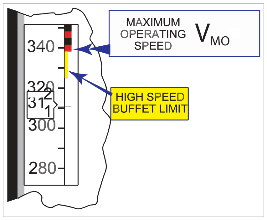
Maximum allowable speed shown by barber's pole:
- Conventional ASI: barber's pole pointer = VMO
- EFIS PFD: barber's pole on airspeed tape
- The barber's pole indicates VMO until MMO becomes limiting, then moves anti-clockwise to show maximum allowable speed
- Climbing at constant IAS: as altitude increases, MMO expressed as IAS will decrease
4. Stall Warning System
Regulatory Stall Warning Margin
Warning Types
- Tactile: Stick shaker — vibrates control column, produces a rattling noise
- Aural: Various tones, synthetic voice
- Visual: Red master WARNING light
- FBW specific: Cricket sound + synthetic voice "STALL" + red WARNING light
System Inputs
- Angle of attack (AoA vanes/probes)
- Flap and slat positions
- Landing gear weight-on-wheels (microswitches)
- Airspeed (from ADC)
AoA sensors located on both sides of the front fuselage to compensate for sideslip/yaw. Flap/slat extension modifies the AoA signal (as they change the pitch attitude for the same lift). During take-off, nosewheel liftoff microswitches make the stall warning system active.
System Outputs
- Stick shaker motor
- AoA indicator aural warning
- Synthetic voice warning
- Red master WARNING light
5. Stall Protection
A stall protection system (different from warning) may be fitted to large commercial aircraft:
- FBW aircraft: Flight computer limits AoA; aircraft cannot approach the stall
- Non-FBW: AFCS advances throttles to full power if deceleration below 1.2 VS
- T-tail aircraft: Stick-pusher pushes control column forward at 2 kt above stall speed → prevents deep stall
6. Angle of Attack Sensing & Probes
Typical stalling angle: 12°–18° for straight wings; up to 30°–40° for swept or delta wings.
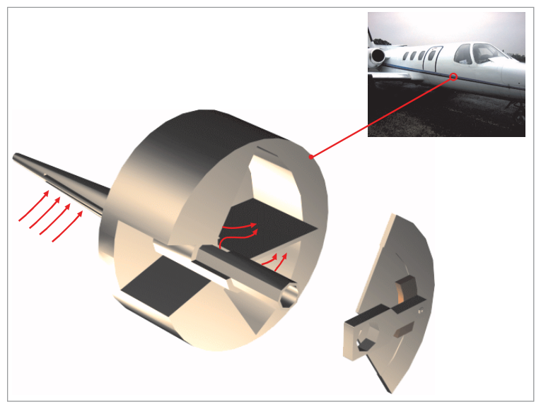
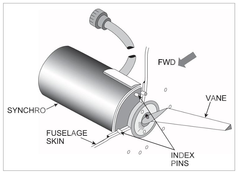
Two Types of AoA Probes
| Type | Description |
|---|---|
| Conical Slotted Probe | Extends through skin perpendicular to airflow. Two sets of slots transmit pressure to paddle chamber; paddle rotates to equalise pressures → positions itself at actual AoA. |
| Vane Detector | Counter-balanced aerodynamic vane positions the rotor of a synchro. Simple, reliable rotating vane. |
AoA probes send information to: stall warning system, ADC, flight envelope protection systems, and AoA indicators.
7. Angle of Attack Indicators
May be fitted in addition to the stall warning system. Provides a direct cockpit display of the current AoA angle, giving the crew continuous situational awareness of proximity to the stalling angle.
8. Configuration Warning (TOCW)
Landing Configuration Warning
Audible warning if throttles are retarded without the landing gear locked down (and may also warn for flaps).
Take-Off Configuration Warning (TOCW)
Sounds if throttles are advanced with any of the following:
- Flaps not in take-off position
- Slats not in take-off position
- Stabilizer trim outside take-off range
- Spoilers/speedbrakes deployed
- Remotely operated flight control locks not disengaged
- External doors/hatches not locked closed
- Parking brake applied
- Altitude alert: Boeing bands 300–900 ft; Airbus 250–750 ft. Inhibited when G/S captured or landing flaps + gear down
- Overspeed: siren + red WARNING + EICAS "OVERSPEED". Cannot be cancelled. Input from ADC. Barber's pole on ASI/PFD
- Stall warning margin: 5 kt or 5% CAS (greater). Must continue until AoA reduced
- Stall warning inputs: AoA, flaps/slats, weight-on-wheels, airspeed
- Stall protection: FBW limits AoA; non-FBW: AFCS advances thrust <1.2VS; T-tail: stick-pusher at 2 kt above stall
- AoA probes: conical slotted OR vane detector; heated; both sides of fuselage; send data to stall warning, ADC, FEP
- Stalling angle: 12°–18° straight wings; up to 30°–40° swept/delta
- TOCW: audible warning when throttles advanced with incorrect T/O configuration
Practice Questions & Detailed Answers
- (a) Autopilot engagement alone does not inhibit altitude alerting.
- (c) Altitude alerting is not inhibited at any particular altitude.
- (d) Radio altimeter failure does not affect barometric altitude alerting.
- (a), (c), (d) None of these describe the actual reason. The design principle is: the hazard persists → the warning persists.
- (a), (c), (d) Incorrect values. The 5/5% rule is the defined standard.
- (a) Redundancy is a benefit, but not the primary positioning reason.
- (c) Both probes measure AoA, not separate parameters.
- (d) While separate systems may feed different displays, dual probe positioning is primarily for sideslip compensation.
- (a) Dutch Roll is controlled by the yaw damper, not a stick-pusher.
- (b) VMO exceedance is addressed by the high speed protection and overspeed warning, not a stick-pusher.
- (d) Porpoising is a landing technique issue, unrelated to stick-pusher.
- (a) Gear DOWN is correct for landing, but at T/O the gear should be down — TOCW does not warn for this.
- (c) TOCW warns when flaps are NOT in T/O position; flaps IN T/O position is correct.
- (d) TOCW warns when trim is OUTSIDE T/O range; within range is correct.
Reinforce Chapter 33: Aerodynamic Warnings
Test your knowledge and practice actual exam questions for Navigation — Instrumentation.