Yaw Dampers
by Ghost Aviator
Table of Contents
- Dutch Roll — The Problem the Yaw Damper Solves
- Why Altitude Worsens Dutch Roll
- Yaw Damper — Purpose and Function
- Yaw Damper System Architecture
- Phase Advance Circuit
- The Dutch Roll Filter
- Rudder Authority and Split Rudder Systems
- Gain Scheduling
- Operating Modes — Synchronisation and Engaged
- LVDT Feedback and Crosswind Compensation
- System Testing
- Practice Questions & Detailed Answers
1. Dutch Roll — The Problem the Yaw Damper Solves
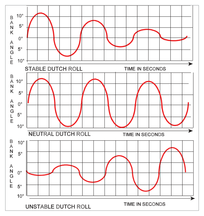
Dutch Roll is an oscillatory motion consisting of a combination of yawing and rolling. It arises from the dynamic interplay between lateral stability and directional stability:
- Strong lateral stability (dihedral effect) rolls the aircraft back from a bank
- Weak directional stability — insufficient yaw correction — allows the nose to swing out of line
- These two tendencies alternate in a coupled yaw-roll oscillation
flowchart LR
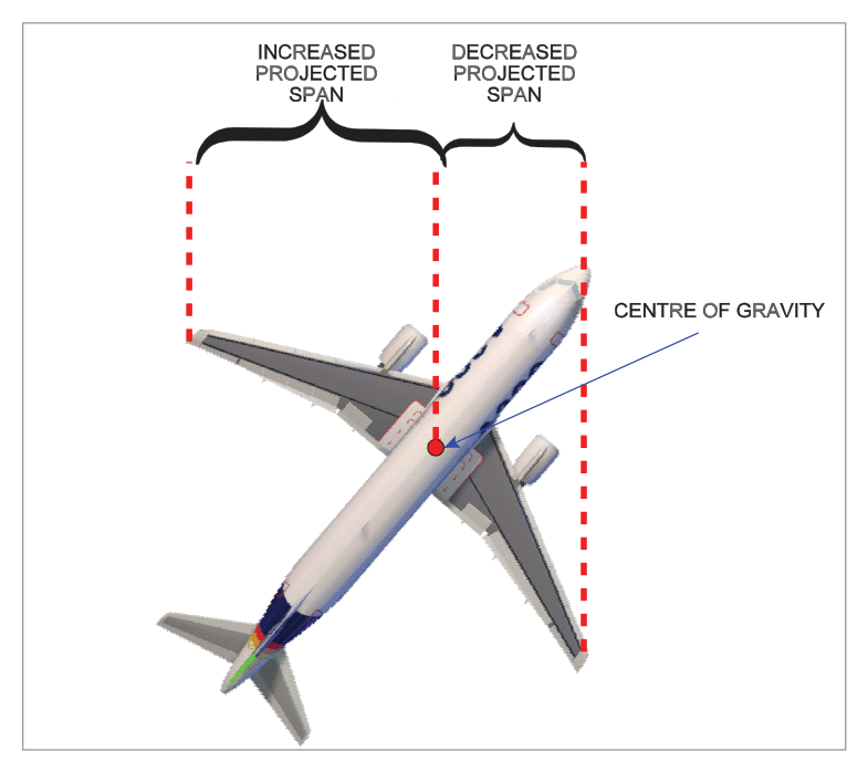
  A["Gust causes yaw\n(nose left)"] --> B["Swept right wing\nadvances, generates\nmore lift → rolls right"]
  B --> C["Strong dihedral effect\nrolls aircraft back left"]
  C --> D["Overswing: nose\nnow swings right"]
  D --> E["Left wing advances\n→ rolls left"]
  E --> F["Cycle repeats\n(Dutch Roll)"]
Why Swept Wings Exacerbate Dutch Roll
Swept-wing aircraft have high dihedral effect (rolling tendency from a yaw disturbance) but relatively low keel surface area for directional damping. This imbalance — strong lateral vs weak directional stability — is the root cause of Dutch Roll susceptibility in jets.
2. Why Altitude Worsens Dutch Roll
At altitude, True Air Speed (TAS) is much higher for the same Indicated Air Speed (IAS). The aerodynamic damping of any oscillation depends on the change in angle of attack (AoA) produced per unit disturbance. At high TAS, the same angular disturbance produces a smaller proportional change in AoA → less aerodynamic damping force.
3. Yaw Damper — Purpose and Function
The yaw damper detects unwanted yaw (Dutch Roll) and applies rapid, small, automatic rudder deflections to damp out the oscillation. Unlike the autopilot rudder channel, the yaw damper operates continuously throughout flight — on during the entire flight from take-off to landing.
Functions of the Yaw Damper
- Primary: Damp Dutch Roll oscillations
- Turn coordination: Keeps the slip ball centred during coordinated turns
- Runway alignment: Assist in aligning aircraft with runway centreline during crosswind landings
- Asymmetric thrust assistance: Reduce sideslip tendency during asymmetric power conditions
4. Yaw Damper System Architecture
flowchart TD
  YR["Rate Gyro\n(detects yaw rate)"] --> YDC["Yaw Damper\nComputer"]
  CADC["CADC / ADC\n(gain scheduling input)"] --> YDC
  RA["Radio Altimeter\n(optional altitude input)"] --> YDC
  YDC --> PA["Phase Advance\nCircuit"]
  PA --> DF["Dutch Roll\nFilter\n(band-pass)"]
  DF --> SER["Rudder Servo\nActuator"]
  SER --> RUD["Rudder\nDeflection"]
  LVDT["LVDT Feedback\n(rudder position)"] --> YDC
Rate Gyro Sensing
The core sensor is a yaw rate gyro that measures the angular rate of yaw. The signal goes through the phase advance circuit before the Dutch Roll filter.
5. Phase Advance Circuit
Dutch Roll oscillation has a natural frequency. If the yaw damper applies a corrective rudder deflection based purely on the instantaneous yaw rate signal, there is a small time delay in the overall loop (signal processing, servo response, rudder surface deflection). By the time the corrective force is applied, the aircraft's yaw rate has already peaked and started to decrease — the correction arrives late, potentially making things worse.
6. The Dutch Roll Filter
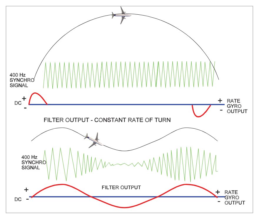
Without filtering, the yaw damper would apply rudder during every yaw input — including deliberate turns. A Dutch Roll Filter (also called a wash-out filter or narrow band-pass filter) is inserted to prevent this.
Filter Characteristics
- Passes only signals at the Dutch Roll frequency (typically 0.3–1 Hz for transport jets)
- Attenuates steady-state yaw signals (constant-rate turns produce a DC signal → zero filter output)
- Attenuates very low frequency (drift) and very high frequency (structural) signals
The filter ensures the yaw damper only damps the oscillatory Dutch Roll component while ignoring steady manoeuvring yaw rates.
7. Rudder Authority and Split Rudder Systems
Rudder Authority per System
Yaw damper rudder deflection authority is limited to prevent excessive rudder inputs that could cause structural overload:
- Typical authority: 3°–6° per yaw damper system
- This is sufficient to damp Dutch Roll without the pilot noticing large rudder pedal movement
Split Rudder
Many transport aircraft have the rudder divided into upper and lower panels, each driven by a separate hydraulic actuator (and a separate yaw damper system). This provides:
- Redundancy — one system failure means half the rudder remains operative
- Fail-safe operation — aircraft retains approximately 50% Dutch Roll damping capability if one system fails
8. Gain Scheduling
At high airspeeds, even small rudder deflections generate large aerodynamic forces. If the yaw damper applies the same rudder deflection at high speed as it does at low speed, the structural loads could be excessive.
The CADC (Central Air Data Computer) provides airspeed/Mach data to the yaw damper computer, which uses this to reduce the gain (sensitivity → rudder deflection per unit yaw rate signal) at high speeds. This is gain scheduling or gain programming:
- Low speed → higher gain (larger rudder deflections needed for adequate damping)
- High speed → lower gain (smaller deflections to prevent overstress)
9. Operating Modes — Synchronisation and Engaged
Synchronisation Mode (Pre-Engagement)
When the yaw damper is about to be engaged, it goes through a synchronisation phase. An inverting integrator circuit is used to cancel any transient rudder deflection that would occur if the system engaged with the aircraft already in a yaw. The synchronisation ensures a smooth, transient-free engagement.
Engaged Mode
Normal operational mode. The yaw damper computer continuously monitors yaw rate from the rate gyro, passes the signal through the phase advance circuit and Dutch Roll filter, and commands the rudder servo to apply corrective deflections.
10. LVDT Feedback and Crosswind Compensation
An LVDT (Linear Variable Differential Transformer) on the rudder surface provides position feedback to the yaw damper computer. This ensures the rudder returns to neutral after each corrective deflection — without this, the rudder would creep off centre.
Crosswind Compensation (Integrator Action)
During a crosswind landing, a constant rudder deflection is needed to maintain the aircraft's heading aligned with the runway. The LVDT feedback loop includes an integrator:
- During normal Dutch Roll damping: the integrator ramps quickly, ensuring rudder returns to neutral
- During a sustained crosswind: the integrator ramps up slowly to maintain the offset rudder position, providing the needed steady-state crosswind correction without fighting the rudder
11. System Testing
Test Procedure
- A Test Switch applies an electrical signal that torques the yaw rate gyro (simulates a yaw input)
- The system reacts by commanding a rudder deflection
- A Position Indicator (yaw damper rudder position indicator) moves in the direction being tested
- When the test switch is released, the indicator returns to centre
- Dutch Roll = coupled yaw-roll oscillation; caused by high dihedral effect + weak directional damping (swept wings)
- Aerodynamic damping decreases at altitude (higher TAS → smaller proportional AoA change)
- Yaw Damper: detects yaw rate → small rapid rudder deflections; operates for entire flight
- Functions: Dutch Roll damping, turn coordination, runway alignment, asymmetric thrust assistance
- Large airliners: 2–3 yaw damper systems
- Phase advance: applies correction at maximum yaw rate for best damping
- Dutch Roll filter: passes only Dutch Roll frequency; zero output during constant-rate turns
- Rudder authority: 3°–6° per system; additive on single rudder span; split rudder = ½ protection if one fails
- Gain scheduling: CADC reduces gain at high speed to prevent overstress
- Synchronisation mode: inverting integrator prevents transient at engagement
- LVDT feedback: ensures rudder returns to neutral; integrator maintains crosswind offset
- Test: test switch torques gyro → indicator moves in tested direction → returns to centre
Practice Questions & Detailed Answers
- (a) Low dihedral effect and high directional stability would actually inhibit Dutch Roll — the directional stability would damp the yaw before rolling develops.
- (c) Low dihedral + low directional = spiral divergence tendency, not Dutch Roll.
- (d) High dihedral + high directional = very stable aircraft; oscillations well-damped.
- (a) The opposite — the filter prevents rudder input during turns.
- (c) Altitude-based gain reduction is the job of gain scheduling using CADC data, not the Dutch Roll filter.
- (d) LVDT feedback ensures the rudder returns to neutral; the filter has no role in this.
- (a) Maximum yaw displacement is a phase-lagged point — correcting here would be less effective and potentially add energy.
- (b) Waiting for a full cycle to complete would allow the oscillation to grow, not damp it.
- (d) Roll through wings level is a lateral event; the phase advance is about yaw rate timing.
- (a) The remaining operative system still provides 50% protection — not zero.
- (b) 75% would imply the failed system contributed only 25%, which is not the case with symmetric split rudder systems.
- (d) 100% protection would require full rudder span authority from a single system.
- (a) Air density decreases at altitude, and lower density means less aerodynamic force — partially correct but not the complete mechanism. The key is TAS vs AoA, not density alone.
- (c) Rate gyros are electromechanical devices; their sensitivity does not meaningfully change with altitude.
- (d) Dihedral effect changes with speed but is not described as increasing specifically with altitude in this context.
- (a) The indicator SHOULD move — that confirms the system responded to the simulated yaw input.
- (c) Staying at the deflected position would indicate LVDT failure (rudder not returning to neutral).
- (d) Phase advance circuit failure would not affect the test indicator's deflection-and-return response.
Master Reference Table — Chapter 29
| Item | Value / Fact | Section |
|---|---|---|
| Dutch Roll cause | High dihedral effect + low directional stability (swept wings) | 1 |
| Altitude effect on damping | Higher TAS → smaller AoA change per disturbance → less aerodynamic damping | 2 |
| Number of yaw damper systems (large airliners) | 2–3 | 3 |
| Yaw damper operation period | Entire flight (take-off to landing) | 3 |
| Rudder authority per system | 3°–6° | 7 |
| Split rudder failure (one system) | ~50% damping protection remaining | 7 |
| Phase advance circuit function | Applies correction at point of maximum yaw rate | 5 |
| Dutch Roll filter | Band-pass — passes Dutch Roll frequency; zero output during constant-rate turn | 6 |
| Gain scheduling | CADC reduces gain at high speed to prevent structural overload | 8 |
| Synchronisation mode | Inverting integrator cancels transient at engagement | 9 |
| LVDT function | Position feedback ensures rudder returns to neutral; integrator maintains crosswind offset | 10 |
| Test: indicator moves then returns to centre | System serviceable | 11 |
Reinforce Chapter 29: Yaw Dampers
Test your knowledge and practice actual exam questions for Navigation — Instrumentation.