Autothrottle
by Ghost Aviator
Table of Contents
- Introduction — What the Autothrottle Does
- Autothrottle System Components
- Boeing 737-400 A/T System
- Power Management Control (PMC)
- A/T Engagement and Disengagement
- A/T Operating Modes
- A/T Warning Lights & Thrust Mode Annunciator
- Flexible Take-off
- Turbulence
- FADEC — Full Authority Digital Engine Control
- Practice Questions & Detailed Answers
1. Introduction — What the Autothrottle Does
An autothrottle system is a computer-controlled, electromechanical system that controls the thrust of an aircraft's engines within specific design parameters. It controls throttle position to maintain a specific value of thrust in terms of:
- Fan Speed (N1)
- Engine Pressure Ratio (EPR), or
- Target Airspeed (set by SPD on mode control panel)
Using the above modes, the autothrottle can control either engine thrust or aircraft speed from the beginning of the take-off roll until disconnection after an automatic landing.
2. Autothrottle System Components
The autothrottle (also called Thrust Management System / TMS) works in conjunction with the autopilot and FMS.
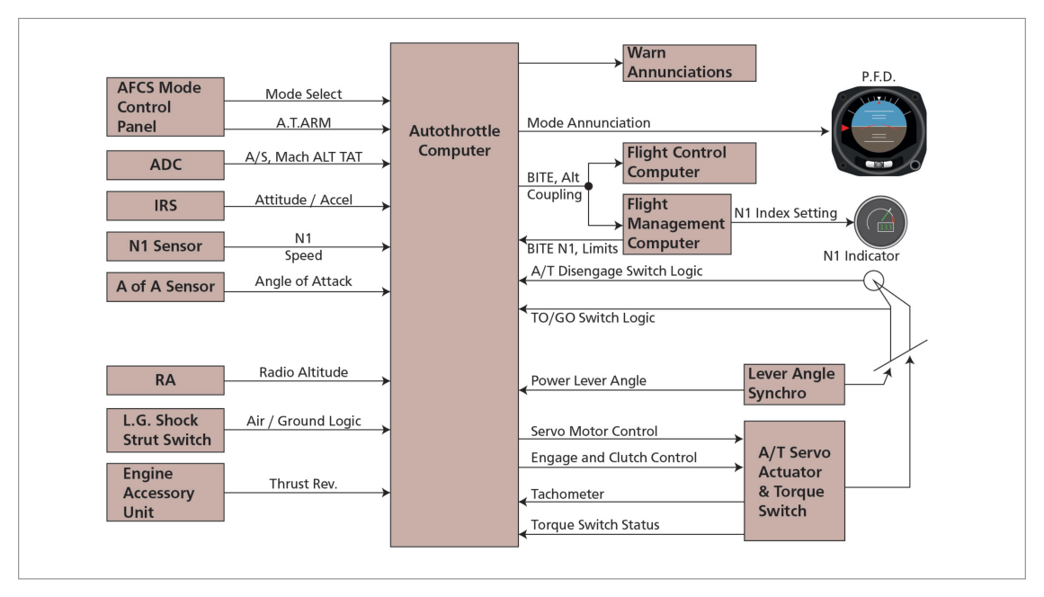
System Inputs
| Input | Source |
|---|---|
| Mode selection & A/T Arm switch | MCP |
| TAS, Mach No., TAT | ADC |
| Attitude and acceleration | IRS |
| N1 speed and/or EPR | Engine sensors |
| Angle of attack | AoA sensor |
| Radio altitude | Radio altimeter |
| Air/ground logic | Landing gear switch |
| Reverse thrust requirement | Engine accessory unit |
| Thrust command | FMS or thrust mode select panel |
| A/T Disconnect switch signal | Throttle levers |
| PLA (power lever angle) | Transducers |
| Flap position | Flap position sensor |
System Outputs
- A/T servo actuator signals to move throttles
- A/T disengage circuit
- BITE circuits (Built-In Test Equipment) in FCC and FMC
- Mode annunciation to EFIS symbol generator
- Thrust limits to EICAS/ECAM display
- Failure warnings (lamp, aural, electronic display)
Feedback
The A/T compares actual values with reference values and passes control signals to servomotors of the thrust levers. Feedback from servo actuators to the Thrust Management Computer (TMC) controls the rate of movement of the thrust levers.
3. Boeing 737-400 A/T System
The A/T provides automatic thrust control from start of take-off roll through to disconnect after landing. In normal operation, the FMC provides the A/T system with N1 limit values.
The A/T moves each thrust lever with a separate servomotor. Manually positioning thrust levers does NOT cause A/T disengagement unless 10 degrees of thrust lever separation is exceeded during a dual channel approach after FLARE is armed. Following manual positioning, the A/T may reposition thrust levers to comply with computed requirements (except in HOLD and ARM modes).
4. Power Management Control (PMC)
The thrust control system consists of a hydromechanical Main Engine Control (MEC) unit and a PMC unit on each engine:
- MEC: Schedules fuel to provide thrust called for by thrust lever setting
- PMC: Further refines fuel flow electronically, without moving thrust levers, using MEC power lever angle, N1 speed, inlet temperature and pressure
PMC Failure
- PMC detects failure → schedules slow N1 drift over approximately 30 seconds → illuminates PMC INOP light + ENG annunciator + MASTER CAUTION lights
- PMC INOP light suppressed below starter cut-out engine speed
- PMC selected OFF on aft overhead panel → engine speed controlled by hydromechanical MEC only
5. A/T Engagement and Disengagement
Moving the A/T Arm switch to ARM arms the A/T for engagement in the N1, MCP SPD, or FMC SPD mode. The switch is magnetically held at ARM and releases to OFF when A/T becomes disengaged.
A/T Disengagement Conditions
- Moving A/T Arm switch to OFF
- Pressing either A/T Disengage switch
- A/T system fault detected
- 2 seconds have elapsed since landing touchdown
- Thrust levers separated by more than 10 degrees during dual channel approach after FLARE is annunciated
- Returning A/T Arm switch to ARM
- Pressing either A/T Disengage light
- Pressing either A/T Disengage switch
6. A/T Operating Modes
flowchart LR
  TO["Take-off\nTO/GA → N1\nAdvances to T/O thrust"] --> THR_HLD["THR HLD at 84 kt\n(A/T cannot change thrust\nbut manual OK)"]
  THR_HLD --> ARM_LIFT["ARM after 400 ft RA\n+ 18 sec post-liftoff\nReduction to climb thrust\nby pressing N1 switch"]
  ARM_LIFT --> N1["N1 Mode\nMaintains FMC N1 limit"]
  ARM_LIFT --> SPD["Speed Mode (MCP SPD)\nMaintains target IAS/Mach"]
  N1 --> RETARD["RETARD\n(LVL CHG / VNAV descent)"]
  SPD --> FLARE_RETARD["RETARD\n2.5 sec after FLARE\nOR at 27 ft RA"]
  FLARE_RETARD --> DISENG["Auto-disengage\n~2 sec after TD"]
Take-off Mode
Engaged by pressing TOGA switch on the ground with A/T armed and desired T/O N1 selected from FMC CDU. A/T annunciation changes from ARM to N1; thrust levers advance toward T/O thrust.
- THR HLD annunciates at 84 kt (earlier computers: 64 kt) — A/T cannot change thrust level position, but thrust levers can be manually repositioned
- After lift-off, THR HLD until 400 ft RA reached AND approximately 18 seconds have elapsed since liftoff
- A/T annunciation then changes to ARM; reduction to climb thrust by pressing N1 switch
- Automatic reduction to climb thrust inhibited until 2½ minutes after lift-off when in LVL CHG or V/S mode
N1 Mode
A/T maintains thrust at the N1 limit selected from FMC CDU. If an engine fails while in N1 mode, the thrust lever of the failed engine will advance a few degrees and then return to or below the other lever position.
Speed Mode (MCP SPD)
Available throughout the flight once take-off phase is complete. A/T maintains the speed shown in the MCP IAS/MACH display. A/T will not set power above the displayed N1 limit. If an engine fails in speed mode, both thrust levers advance together to maintain target speed.
Do NOT set higher command speed to allow for wind/gust corrections — A/T corrects for normal wind gusts through airspeed and acceleration sensing. Higher command speeds cause excessive approach speeds.
Below 400 ft RA: A/T thrust response rate and engine power levels are sufficient to place engines in the rapid acceleration range.
FMC Speed Mode
A/T mode commanded by FMC during V NAV operation. MCP IAS/Mach display is blank; airspeed cursors positioned at FMC commanded airspeed. A/T limited to N1 value shown on thrust mode annunciators.
N1 Equalization
The A/T attempts to equalize N1 through dual servo individual thrust lever control. Equalization control is limited to 8 degrees of thrust lever separation.
ARM Mode
Annunciated ARM when A/T Arm switch is at ARM and no A/T mode is engaged. Thrust levers can be manually positioned without A/T interference.
Descent Retard Mode
A/T engages and annunciates RETARD during LVL CHG and V NAV descents. RETARD changes to ARM when thrust levers reach aft stop or are manually prevented from reaching it.
Landing Flare Retard Mode
RETARD mode engages and reduces thrust 2½ seconds after FLARE mode engagement OR at 27 ft RA, whichever occurs first. Also engages at 27 ft RA during non-precision/visual approach with flaps ≥15° and AFDS not in ALT ACQ or ALT HOLD. A/T auto-disengages approximately 2 seconds after landing touchdown.
Go-around Mode
A/T GA mode is armed when descending below 2000 ft RA (with or without AFDS). Once armed, can be engaged until 2 seconds after landing touchdown.
- Pressing either TOGA switch → GA annunciated; thrust levers advance to reduced GA thrust setting (produces 1000–2000 fpm rate of climb)
- Pressing TOGA a second time after reaching reduced GA thrust → A/T advances to full GA N1 limit
- During single-engine FD go-around → A/T increases thrust to full N1 limit
7. A/T Warning Lights & Thrust Mode Annunciator
| Light State | Meaning |
|---|---|
| Flashing Red | A/T disengaged for any reason |
| Steady Red | Disengage Light Test Switch position 2 (red filament test) |
| Steady Amber | Disengage Light Test Switch position 1 (amber filament test) |
| Flashing Amber | A/T airspeed error: speed not held within +10 / –5 knots of commanded speed (when in MCP SPD or FMC SPD, in flight, flaps not up) |
Thrust Mode Annunciator (TMA) Panel
Located on the centre instrument panel above N1 rpm indicators (737-400). Displays the active N1 limit reference mode for both autothrottle and manual thrust control.
8. Flexible Take-off
When take-off can be performed without full engine power (e.g., light weight, long runway), reduced power may be used to reduce engine wear and increase engine life. This is the Flexible Take-off mode (FLEX TO on Airbus).
Achieving Reduced Thrust with A/T
Select a temperature on the control panel that is higher than the ambient airfield temperature. The thrust computation system calculates a lower limiting EPR or N1, producing reduced power for take-off.
9. Turbulence
10. FADEC — Full Authority Digital Engine Control
FADEC Functions
- Gas generation control (fuel flow, acceleration/deceleration, variable bleed valves/stator vanes, turbine clearance, idle setting)
- Engine limit protection (over-speed N1 and N2)
- Power management (thrust rating, thrust parameter limits, auto-thrust demand, manual TLA demand)
- Automatic engine starting sequence (start valve, fuel, ignition, monitoring N1/N2/FF/EGT)
- Manual engine starting sequence (passive monitoring)
FADEC Advantages
- Reduces crew workload
- Engine limit protection
- Improves engine life
- Saves fuel and maintenance downtime
FADEC Components
Electronic Engine Control (EEC) + fuel metering unit + sensors + peripheral units. Two FADEC channels per engine (one controlling, one standby — redundancy).
- Powered by aircraft AC supply before and during initial start
- Above 12% engine rpm: powered by individual internal magnetic alternator
FADEC Thrust Lever Detents (Airbus)
Thrust levers only moved manually (unlike many autothrottle systems). Lever sector divided into 4 segments by 5 detents/stops. Thrust lever position transmitted to FADEC which computes and displays thrust rating limit and N1 TLA. No reverse idle detent — reverse idle selected by pulling up reverse thrust levers to clear the idle stop.
- Thrust lever in a detent → FADEC selects rating limit corresponding to that detent
- Thrust lever between 2 detents → FADEC selects rating limit corresponding to the higher mode
FADEC Fuel Control
HMU (Hydromechanical Unit) — modulated by FADEC; provides fuel flow control to combustion chamber, hydraulic signals to actuators, and over-speed protection.
FMV (Fuel Metering Valve) — transforms FADEC orders into fuel flow via torque motor/servo valve. FMV resolver provides electrical feedback proportional to FMV position.
FADEC computes fuel flow to hold target N1. Allows N2 to vary (within limits) to maintain lift, bleed air, and avoid engine stall/flameout. FADEC also modulates cooling airflow around engine casing to control compressor/turbine clearances.
FADEC Thrust Control — Automatic Mode
In auto-thrust mode (A/THR function active), thrust is computed by the FMGC and limited to value corresponding to thrust lever position (except during alpha floor activation).
- A/T controls N1, EPR, or target airspeed; no direct thrust indicator exists
- A/T operates from start of take-off roll to ~2 seconds after touchdown
- THR HLD engages at 84 kt; clears at 400 ft RA + 18 sec after liftoff
- A/T auto-disengages: OFF switch, disengage switch, system fault, 2 sec after TD, 10° lever separation in dual approach after FLARE armed
- Recommended approach speed: VREF + 5 kt — do not add extra for gusts (A/T does this automatically)
- GA mode: armed below 2000 ft RA; first TOGA = reduced GA thrust; second TOGA = full GA N1
- A/T flashing amber = airspeed error ±10/–5 kt of commanded speed
- A/T LIM: FMC N1 invalid OR engine N1 < 18%
- Flexible T/O: select higher assumed temperature → lower N1/EPR limit → reduced thrust
- Turbulence: A/T OK in light-moderate (expect ±10–15 kt excursions); NOT used in severe turbulence
- FADEC: 2 channels per engine; powered by A/C supply then by magnetic alternator above 12% rpm
- FADEC between detents: selects higher mode rating limit
Practice Questions & Detailed Answers
- (a) 60 kt is the FD pitch change threshold (Chapter 25), not the A/T THR HLD trigger.
- (c) 400 ft RA is when THR HLD is cleared, not when it engages.
- (d) V2 + 20 kt is the FD target speed reference, not an A/T threshold.
- (a) 5 degrees is too small; minor lever separation is tolerated.
- (b) 8 degrees is the N1 equalization limit, not the A/T disengage threshold.
- (d) 15 degrees exceeds the actual threshold — A/T would already have disengaged.
- (a) VREF alone, without the +5 kt buffer, is not recommended.
- (c), (d) Adding excessive speed above VREF + 5 kt causes excessive approach speeds; the A/T handles gusts automatically.
- (a) Second TOGA press does not disengage the A/T.
- (b) Advancing to idle is the opposite of a GA requirement.
- (d) Remaining at reduced GA thrust is what happens before the second TOGA press.
- (a), (c), (d) These are fabricated expansions of the acronym. "Full Authority" is critical — it means the system has complete (full) authority over engine control, unlike partial authority systems.
- (a) Manual lever positioning is the most basic reduced-thrust method, but not how the A/T achieves flexible take-off.
- (c) N1 limits on EICAS are computed outputs, not direct control inputs for flexible T/O.
- (d) Reducing fuel flow on the FMC CDU is not a standard flexible T/O procedure.
Master Reference Tables
Key Numerical Values — Chapter 28
| Value | Parameter | Section |
|---|---|---|
| 84 kt | THR HLD engagement IAS (earlier computers: 64 kt) | 6 |
| 400 ft RA + 18 sec | THR HLD clearance after liftoff | 6 |
| 2½ min | Automatic climb thrust reduction inhibited when in LVL CHG or V/S mode | 6 |
| VREF + 5 kt | Recommended A/T approach command speed | 6 |
| 400 ft RA | Below this RA: thrust response rate sufficient for rapid acceleration | 6 |
| 2 sec | A/T auto-disengages this long after touchdown | 5 |
| 10° | Thrust lever separation causing A/T disengage (dual approach, FLARE armed) | 5 |
| 8° | N1 equalization limit (thrust lever separation) | 6 |
| 2½ sec | After FLARE engagement before RETARD engages (or 27 ft RA, whichever first) | 6 |
| 2000 ft RA | GA mode arms below this RA | 6 |
| 1000–2000 fpm | Rate of climb achieved at reduced GA thrust | 6 |
| +10/–5 kt | A/T amber flashing threshold (airspeed error from commanded speed) | 7 |
| 150 sec | Minimum after liftoff for amber auto-test to occur | 7 |
| 18% | Engine N1 below which A/T LIM annunciates | 7 |
| 10–15 kt | Airspeed excursions expected in light-moderate turbulence with A/T engaged | 9 |
| 12% rpm | Engine speed above which FADEC powers from internal magnetic alternator | 10 |
| 30 sec | PMC failure slow N1 drift duration before INOP light | 4 |
Reinforce Chapter 28: Autothrottle
Test your knowledge and practice actual exam questions for Navigation — Instrumentation.