The Airspeed Indicator (ASI)
by Ghost Aviator
Table of Contents
1. Principle of Operation
An aircraft on the ground in still air experiences only static (atmospheric) pressure. In flight, the leading edges of the aircraft are subject to an additional dynamic pressure due to relative motion through the air. The pitot head senses the total (pitot) pressure; the static vent senses static pressure only.
Where: ρ = air density; V = True Airspeed (TAS).
The ASI is a differential pressure gauge that measures the difference between pitot and static pressures (i.e. dynamic pressure), displaying the result in knots on a calibrated scale. (1 knot = 1 nautical mile per hour.)
2. Construction
Static pressure is fed into a hermetically-sealed instrument case. Pitot pressure is piped to a thin metal capsule inside the case capable of expansion and contraction.
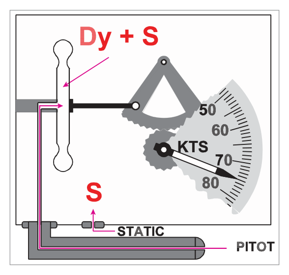
Static pressure acts on both the inside of the case and the outside of the capsule walls, so it cancels. The pressure differential across the capsule wall is therefore:
Capsule expansion/contraction is proportional to changes in dynamic pressure (= changes in airspeed). The movements are transmitted via a temperature-compensated magnifying linkage to the pointer on the ASI face.
3. Calibration
Dynamic pressure depends on both speed and air density. Density varies with temperature and pressure, and therefore with altitude. The ASI is calibrated to read True Airspeed for the ISA MSL conditions only:
| Calibration Condition | Value |
|---|---|
| Air density | 1225 g/m³ |
| Pressure | 1013.25 hPa |
| Temperature | +15°C |
| Humidity | Dry air |
No allowance is made for the change in density with altitude. Flight at any condition other than ISA MSL therefore introduces errors. The ASI accuracy tolerance (CS-25) is ± 3% or 5 kt, whichever is greater.
4. ASI Errors & Airspeed Definitions
4.1 Indicated Airspeed (IAS)
The reading directly off the instrument face. Affected by all errors below.
4.2 Instrument Error
Manufacturing imperfections and wear cause small errors determined under laboratory conditions using a datum instrument. A correction card is produced for the speed range of the instrument and placed near the ASI in the cockpit.
4.3 Position Error (Pressure Error)
Arises mainly from sensing incorrect static pressure due to the probe’s location on the aircraft. Position errors vary across the speed range and are determined during the manufacturer’s flight test programme. In practice, a combined Instrument + Position Error correction card is used.
4.4 Manoeuvre-Induced Error
Associated with changes in angle of attack, producing transient errors and lag in airspeed indication. Primarily affects rapidly changing flight conditions.
4.5 Calibrated Airspeed (CAS)
Also historically known as Rectified Airspeed (RAS) (no longer in general use, but may appear on the Pooley CRP-5).
Example: If combined correction is +2 kt and pilot wants 100 kt CAS, fly at 98 kt IAS.
Why CAS matters: Aircraft stress limits and stall speeds are functions of dynamic pressure. Because the ASI is calibrated in “knots” (true only at ISA MSL), CAS provides a consistent measure of dynamic pressure regardless of altitude and density. Stall and structural limit speeds are expressed as CAS/IAS values.
4.6 Density Error
At altitudes above MSL, air density is less than 1225 g/m³ (the calibration density). Less dense air produces less dynamic pressure for the same TAS. The capsule expands less, and the ASI under-reads the true speed. If density is greater than ISA at MSL, the ASI over-reads.
4.7 Compressibility Error
Air is compressible; at speed the pressure in the pitot tube is higher than for an ideal incompressible fluid (for which dynamic pressure = ½ρV²). The ASI is calibrated for compressible flow at ISA MSL density. At lower densities (higher altitude), the standard compressibility correction becomes incorrect and the instrument over-reads (IAS and CAS too high). A subtractive compressibility correction must be applied.
4.8 Equivalent Airspeed (EAS)
EAS is the most accurate measure of dynamic pressure over the wing. All structural limit speeds are calculated from EAS; errors are then re-introduced to display them as IAS. At constant weight, an aircraft always lifts off at a constant EAS regardless of altitude.
In practice the difference between EAS and CAS is not large unless altitude is significant. However, at high-elevation airports with high-performance aircraft, CAS (and IAS) will be higher than EAS for the same dynamic pressure condition.
4.9 True Airspeed (TAS)
TAS is the actual speed of the aircraft relative to the surrounding air mass. It is the speed used for navigation and flight planning.
Density must be calculated from pressure (altitude) and temperature together — there is no direct density instrument. The navigational computer combines altitude and temperature to derive the density correction. The major factor is the pressure value.
5. Airspeed Correction Sequence — IAS to TAS
flowchart LR
    A["IAS\n(Indicated Airspeed)\nRaw instrument reading"] -->|"+ Instrument Error\n+ Position Error"| B["CAS\n(Calibrated Airspeed)"]
    B -->|"+ Compressibility\nCorrection"| C["EAS\n(Equivalent Airspeed)"]
    C -->|"+ Density\nCorrection"| D["TAS\n(True Airspeed)"]
    style A fill:#e8f1fb
    style B fill:#e8f1fb
    style C fill:#e8f5e9
    style D fill:#e8f5e9
- Apply Density Error correction first → gives TAS.
- If TAS ≤ 300 kt: no compressibility correction needed. STOP.
- If TAS > 300 kt: apply Compressibility Error correction as well.
6. Limiting Speeds & ASI Colour Coding
6.1 Limiting Speed Definitions
| Symbol | Name | Shown on ASI | Description |
|---|---|---|---|
| VNE | Never Exceed Speed | Yes — Red radial line | Absolute maximum; exceeding causes structural failure risk |
| VNO | Maximum Normal Operating Speed | Yes — Top of green arc | Must not be exceeded except in smooth air |
| VFE | Maximum Flap Extension Speed | Yes — Top of white arc | Maximum speed with flaps extended |
| VS0 | Stall Speed (landing config) | Yes — Bottom of white arc | Stall with full flap, gear down, max AUW |
| VS1 | Stall Speed (specified config) | Yes — Bottom of green arc | Stall with flaps up, max AUW |
| VYSE | Best Rate of Climb (one engine) | Optional — Blue radial line (piston twins) | Best rate of climb with one engine inoperative, max weight, MSL |
| VLO | Max Gear Operation Speed | Not on ASI | Max speed for extending or retracting gear |
| VLE | Max Speed with Gear Extended | Not on ASI | Max speed with gear down and locked |
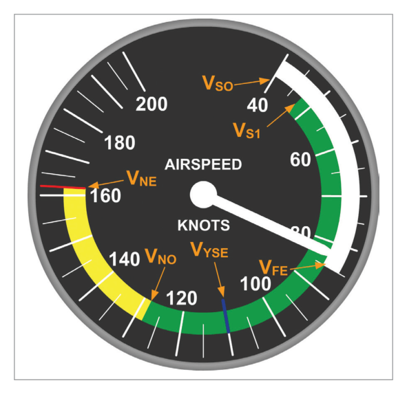
6.2 Colour Arc Coding
| Colour | Range | Meaning |
|---|---|---|
| White Arc | VS0 to VFE | Flap operating range. Safe to extend flaps within this arc. |
| Green Arc | VS1 to VNO | Normal operating range. Safe in all conditions including turbulence. |
| Yellow Arc | VNO to VNE | Caution range. Operate in smooth air only. |
| Red Radial Line | VNE | Never exceed speed — absolute limit. |
| Blue Radial Line | VYSE | Optional. Best single-engine rate-of-climb speed (piston twins). |
7. Pitot and Static Blockages
7.1 Pitot Head Blockage
If the pitot head becomes blocked (typically by ice or insects), the pressure locked inside the capsule remains constant.
- Level flight: Any change in airspeed will not be registered — the ASI freezes at its last reading.
- Climb with blocked pitot: Static pressure around the capsule decreases (as altitude increases). With pitot locked, (pitot − static) increases → ASI over-reads. IAS increases during a climb.
- Descent with blocked pitot: Static pressure increases. With pitot locked, (pitot − static) decreases → ASI under-reads. IAS decreases during a descent.
Special case: If both the ram air input AND the drain hole are blocked (static port open), the locked pitot pressure causes the ASI to react like an altimeter — reading increases during a climb and decreases during a descent.
7.2 Static Head/Vent Blockage
A blocked static source freezes the static pressure at the value existing when the blockage occurred.
- Descent with blocked static: True external static pressure is higher than the frozen value. The capsule experiences (pitot − locked lower static) → larger differential → ASI over-reads. Dangerous: aircraft is closer to stall than indicated.
- Climb with blocked static: True external static pressure is lower than the frozen value. ASI under-reads.
If the alternative static source is selected, an error due to position error may occur. Turbulence effects usually result in higher static pressure at the alternate source, causing an under-reading. This error is documented in the Flight Manual.
Pitot blocked: Under-reads in Descent
Static blocked: Over-reads in Descent
flowchart TD
    A["Blockage\nDetected?"] -->|Pitot| B["During Climb?\nASI over-reads\n(IAS rises)"]
    A -->|Pitot| C["During Descent?\nASI under-reads\n(IAS falls) ⚠"]
    A -->|Static| D["During Climb?\nASI under-reads\n(IAS falls)"]
    A -->|Static| E["During Descent?\nASI over-reads\n(IAS rises) ⚠ DANGER"]
    style E fill:#fdecea
    style C fill:#fff8e1
8. Pitot and Static Leaks
8.1 Pitot Leak
A leak in the pitot line causes loss of dynamic pressure → ASI under-reads.
8.2 Static Leak — Unpressurised Aircraft
In an unpressurised aircraft, if the static leak occurs where the outside pressure is lower than the sensed static pressure (almost always the case aerodynamically), a false lower pressure is sensed around the capsule. The differential (pitot − leaked static) increases → ASI over-reads (usually not significantly).
8.3 Static Leak — Pressurised Aircraft
9. Serviceability Checks
- Pressure head cover(s) and static vent plug(s) removed and stowed aboard.
- Pitot tube(s), holes/slots in static head(s) and static vent(s) checked free from obvious obstructions (insects, debris).
- Pitot head heater operative (if fitted).
- Dial glass clean and undamaged.
- Instrument should indicate airspeed in the correct sense shortly after starting the take-off run.
- ASI measures dynamic pressure = ½ρV² = pitot − static. Calibrated for ISA MSL: 1225 g/m³, 1013.25 hPa, +15°C.
- ASI accuracy tolerance (CS-25): ±3% or 5 kt, whichever is greater.
- Correction chain: IAS → (instrument + position error) → CAS → (compressibility) → EAS → (density) → TAS.
- If TAS ≤ 300 kt: compressibility correction not needed.
- Stall/stress limits are functions of dynamic pressure → expressed as CAS/IAS values.
- At constant weight, aircraft always lifts off at constant EAS regardless of altitude.
- Colour arcs: White = flap range (VS0–VFE); Green = normal ops (VS1–VNO); Yellow = caution (VNO–VNE); Red line = VNE; Blue line = VYSE (piston twins).
- PUDSOD: Pitot blocked → Under-reads in Descent; Static blocked → Over-reads in Descent.
- Pitot leak → under-reads. Static leak (unpressurised) → over-reads. Static leak (pressurised) → ASI useless.
Practice Questions & Detailed Answers
- (a) and (c) These describe effects of blockages, not leaks. A leak consistently reduces dynamic pressure; it does not alternate with flight phase.
- (b) Over-reading occurs with a static leak in an unpressurised aircraft, not a pitot leak.
- (a) and (b) These would apply to a partial pitot blockage. Complete blockage of both input and drain hole seals the system.
- (d) The ASI would not freeze at zero; it would continue to respond to changes in static pressure.
- (b) and (c) Under-reading occurs with a blocked pitot in a descent, or a blocked static during a climb.
- (d) Over-reading is correct but the consequence described is wrong. Over-reading during approach means the aircraft is closer to stall than shown, not that flap speed limits are at risk (that would be from an under-reading).
- (a) CAS is held constant by the question premise.
- (b) EAS is essentially equal to CAS at moderate speeds; it also stays approximately constant if CAS is constant.
- (d) TAS decreases if density increases (cold air). Warmer air → lower density → higher TAS, not lower.
- (a) ISA at all heights would require the ASI to correct for density at every altitude — it does not.
- (c) 1013.25 is the pressure in hPa, not the calibration density. The density is 1225 g/m³.
- (d) The ASI cannot indicate correctly in any atmosphere — density error means it under-reads above ISA MSL conditions.
- (b) Squares ρ instead of V — incorrect formula.
- (c) Squares the product (½ρV) — incorrect.
- (d) Squares the product (ρV) — incorrect.
- (a) Omits compressibility error, which is significant above 300 kt TAS.
- (b) “Temperature error” is not a separate ASI error — it is subsumed within density error (density is a function of both pressure and temperature).
- (c) Barometric error and lag apply to the altimeter, not the ASI.
- (a) Yellow = caution is correct; but the second part says “normal operating range” which is the GREEN arc, not white.
- (b) Reverses the two — flap range is white, not yellow.
- (d) Reverses the order; question asks yellow THEN white, answer (d) states flap range (white) first, then caution (yellow).
- (a) The ASI increasing regardless of airspeed would be the behaviour of a blocked pitot in a climb (not blocked static).
- (c) Over-reading with blocked static occurs in a descent, not a climb (PUDSOD: SOD = Static Over-reads in Descent).
- (d) The reading does not stick — it diverges progressively from actual as altitude changes.
Master Reference Tables — Chapter 4
Numerical Values
| Value | Parameter | Section |
|---|---|---|
| 1225 g/m³ | ASI calibration density (ISA MSL) | 3 |
| 1013.25 hPa | ASI calibration pressure (ISA MSL) | 3 |
| +15°C | ASI calibration temperature (ISA MSL) | 3 |
| ±3% or 5 kt | ASI accuracy tolerance (CS-25) — whichever is greater | 3 |
| 300 kt TAS | Threshold below which compressibility error can be ignored | 4 |
| >20 kt | Maximum compressibility correction near speed of sound | 4 |
Airspeed Definitions Summary
| Term | Definition | Use |
|---|---|---|
| IAS | Raw instrument reading | Initial reading |
| CAS (= RAS) | IAS ± instrument & position error | Stall & structural limits; flying the aircraft safely |
| EAS | CAS − compressibility error | Most accurate dynamic pressure; structural limit calculations |
| TAS | EAS ± density correction | Navigation, flight planning |
PUDSOD Reference
| Blockage | Climb | Descent |
|---|---|---|
| Pitot | Over-reads | Under-reads (PUDSOD — PUD) |
| Static | Under-reads | Over-reads (PUDSOD — SOD) |
Colour Arc Summary
| Colour | Speed Range | Meaning |
|---|---|---|
| White Arc | VS0 to VFE | Flap operating range |
| Green Arc | VS1 to VNO | Normal operating range (safe in turbulence) |
| Yellow Arc | VNO to VNE | Caution (smooth air only) |
| Red Radial Line | VNE | Never exceed |
| Blue Radial Line | VYSE | Best single-engine ROC (piston twins, optional) |
Source Answer Key
| Q1 | Q2 | Q3 | Q4 | Q5 | Q6 | Q7 | Q8 | Q9 |
|---|---|---|---|---|---|---|---|---|
| d | c | a | c | b | a | d | c | b |
Reinforce Chapter 4: The Airspeed Indicator (ASI)
Test your knowledge and practice actual exam questions for Navigation — Instrumentation.