Flight Director Systems
by Ghost Aviator
Table of Contents
- Introduction — Purpose of the FDS
- FDS Information Sources
- Flight Director System Components
- Raw vs Computed Information
- FD Fail Indications
- Flight Director Modes
- Navigation Modes
- FD Take-off Mode
- FD Go-around Mode
- FD Manoeuvre Protection & Gain Scheduling
- Dual FDS & Comparator
- Practice Questions & Detailed Answers
1. Introduction — Purpose of the FDS
The Flight Director System (FDS) was originally developed as an aid to the pilot during landing. It provides steering and attitude signals on one instrument, reducing workload. As autopilots became more advanced, FDS signals could be coupled to the autopilot for more complex tasks.
With an FDS, information about attitude, heading and flight path can be integrated with navigation information to produce:
- Easy-to-interpret visual instructions for the pilot (via flight director bars), and/or
- Direct input to the autopilot, or both simultaneously
2. FDS Information Sources
| Input | Source |
|---|---|
| Airspeed, altitude, VSI | Pitot-Static system or Air Data Computer (ADC) |
| VOR / ILS tracking | VHF Nav receiver |
| Navigation/routing | FMS, INS/IRS |
| Attitude (older) | Gyro-magnetic compass + vertical gyro system |
| Attitude (modern) | INS/IRS (replaces vertical gyro) |
3. Flight Director System Components
Electronic Attitude Director Indicator (EADI)
A standard artificial horizon providing pitch and roll. The Director part comes from its ability to display demand information from the FDS using Flight Director Command Bars. The pilot "flies to" either the intersection of the cross-bars or the point between wedge-shaped pointers. Both displays are intuitive and functionally identical.
Primary Flight Display (PFD)
Part of EFIS — brings all flying information onto one display. Contains EADI surrounded by speed, altitude and VSI tapes plus a compass display. Includes the Flight Mode Annunciator (FMA) area.
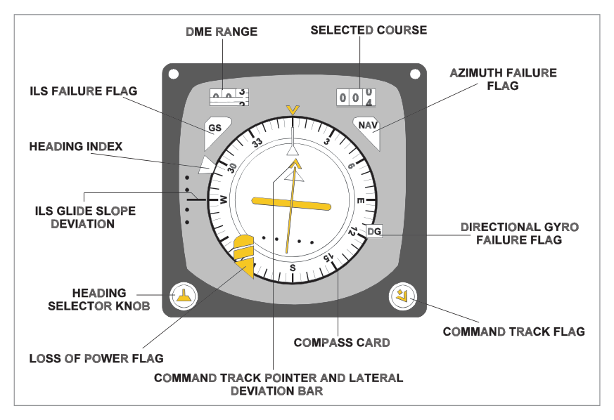
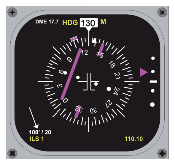
Electronic Horizontal Situation Indicator (EHSI)
A gyro-magnetic compass display with:
- Course Deviation Indicator (CDI) bar
- Deviation dots (scale varies)
- From/to pointer
- Selected course window
- DME display of range
- Heading bug
Modern aircraft use a Navigational Display (ND) and a centralized Autoflight Mode Control Panel (AMCP / MCP) for course selection rather than a knob on the HSI.
Flight Director Computer (FDC)
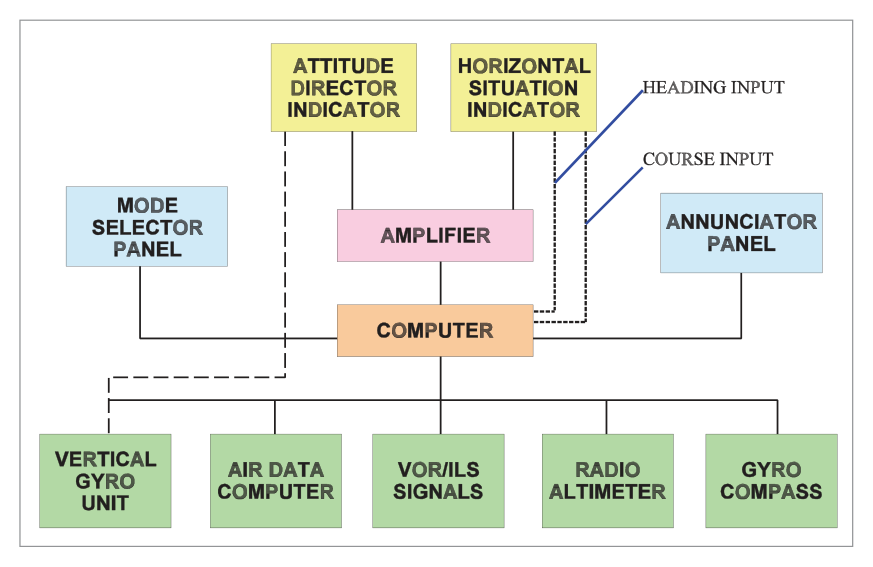
Gathers and processes all inputs. Older aircraft use analogue ADC/VG outputs; modern systems are purely digital. Outputs go to symbol generators for EADI/EHSI and/or the autopilot.
Optional Components
| Component | Function |
|---|---|
| Instrument Amplifier / Symbol Generator | Drives electromechanical instrument motors; feeds EFIS symbol generators on modern aircraft |
| Vertical Gyro (VG) | Remote gyro providing attitude reference on older/smaller aircraft without INS/IRS |
| INS/IRS | Replaces VG on modern aircraft; more sensitive, near aircraft C of G |
| Mode Controller / MCP | Allows pilot to change FDS mode, alter pitch trim, switch FDS display on/off |
| Mode Annunciators / FMA | Shows current FDS/autopilot mode and phase |
FMA (Flight Mode Annunciator) on EFIS Aircraft
- Engaged modes — top line, shown in green
- Armed modes — second line, shown in white
- Newly changed mode — surrounded by a box for emphasis
On older annunciator panels: LOC light = amber (armed) → green (captured). GS light = amber (armed) → green (captured).
4. Raw vs Computed Information
| Type | Description | Source |
|---|---|---|
| Raw Information | Unprocessed; shows aircraft deviation left/right of track or above/below GS in degrees | ILS glide slope indicator, CDI bar |
| Computed Information | Processed from rate of change of deviation; anticipates turns/climbs/descents for smooth flying | FDC output to command bars |
5. FD Fail Indications
| Flag/Warning | Failure Indicated | Location |
|---|---|---|
| "GYRO" warning flag | Vertical gyro or vertical reference system failure, or power supply failure | ADI |
| "ATT" or "FD" flag | FDC failure, instrument amplifier failure, or ADI failure | ADI |
| "GS" flag | Glide slope information unreliable or system failure | GS scale on ADI or HSI |
| "NAV" flag | Poor reception, unreliable or loss of VOR, LNAV or LOC information | HSI |
| Power failure flag | Loss of power to HSI or compass gyro; also indicates DG mode | HSI |
6. Flight Director Modes
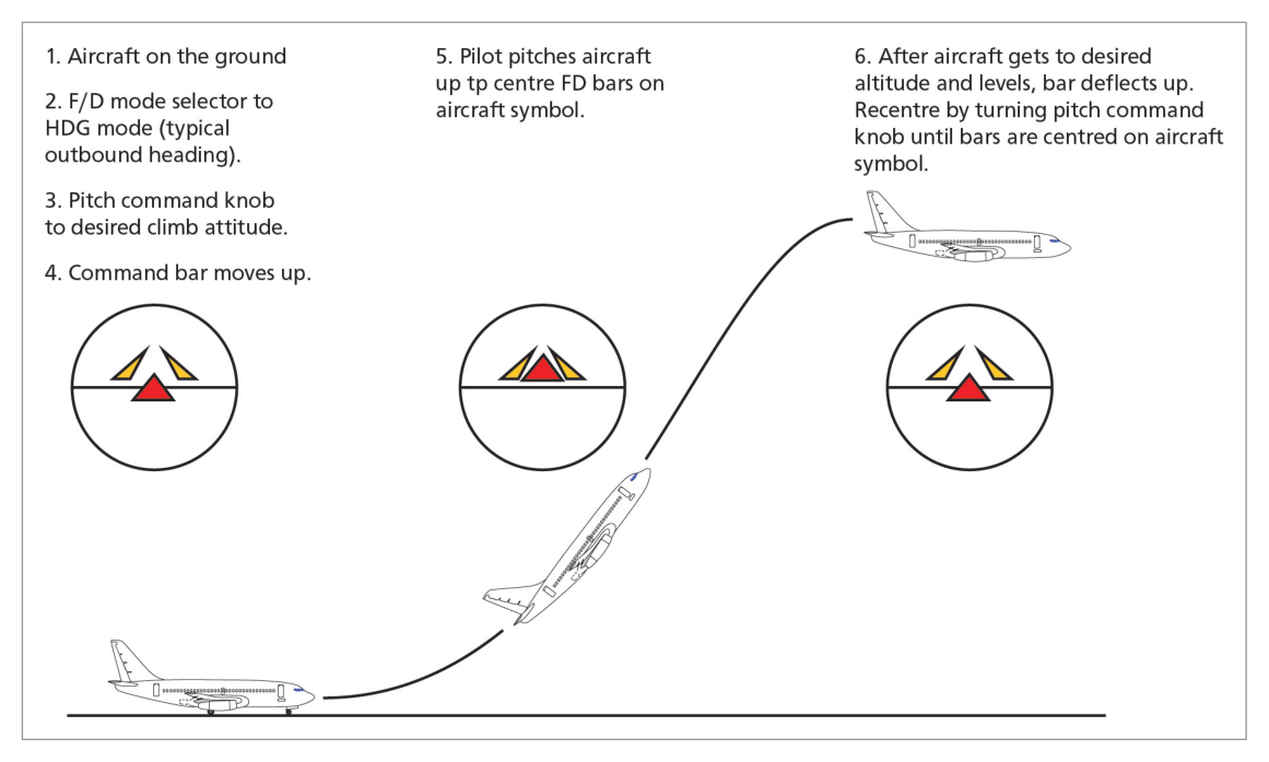
Command Attitude Changes
The FD command bars can be offset vertically to provide an aiming point for maintaining a constant pitch angle (level flight, climb, or descent). Achieved by moving the Pitch Trim knob/wheel. Pitch trim is inhibited whenever any other pitch mode is active.
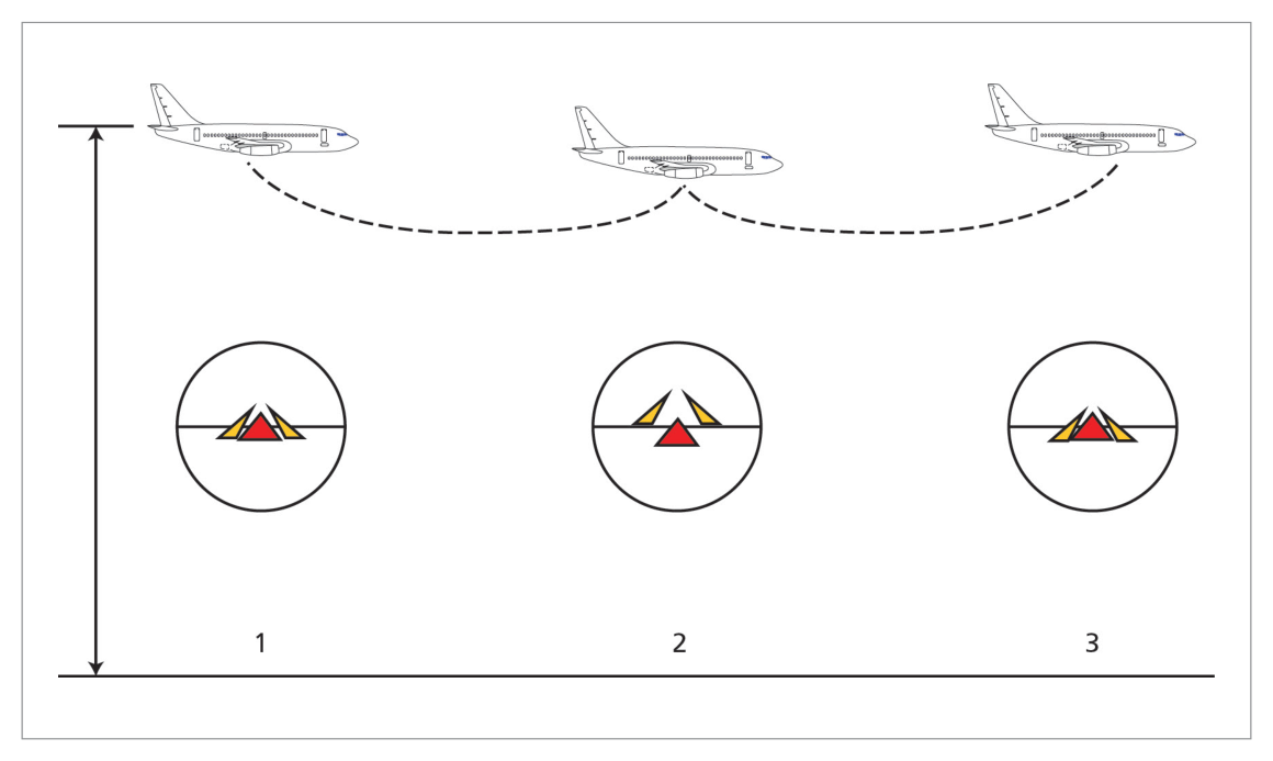
Altitude Acquire / Altitude Hold
Signals from ADC through FDS maintain selected level. If aircraft deviates above desired altitude, FD commands pitch down; if below, it commands pitch up. Command bars indicate neutral position at selected level.
7. Navigation Modes
Heading Mode
Pilot selects desired heading via knob on HSI, MCP, or central panel. FDS indicates a fly-to command to bring aircraft onto desired heading.
LOC / VOR (LNAV)
Allows VOR, Localizer, or INS/IRS/FMS/GPS nav information to be fed and displayed on the FDS. After tuning/identifying the VOR, selecting desired track and VOR/LOC on the mode selector, the FDS gives steering commands to intercept and maintain track.
Flight Director Approach (FDA)
ILS frequency is tuned and identified; QDM set in the course window; mode selector set to AUTO/APP. Sequence:
flowchart TD
  A["APP mode selected\nAnnunciator shows LOC armed"] --> B["Localizer captured\nAnnunciator shows LOC (green)"]
  B --> C["Approaching GS\nAnnunciator shows GS armed (amber)"]
  C --> D["GS captured\nAnnunciator shows GS (green)\nFDS commands nose-down pitch"]
  D --> E["Continue ILS approach\nGain scheduling applied as\naircraft nears threshold"]
8. FD Take-off Mode
Both FD systems should be switched on prior to starting the take-off roll. Take-off mode is engaged by pressing a TO/GA switch on the throttles.
Take-off FD Commands
| Phase | FD Pitch Command | FD Roll Command |
|---|---|---|
| Initial (before 60 kt) | 10° nose-down | Wings level |
| After 60 kt IAS | 15° nose-up | Wings level |
| After lift-off | Maintain 15°NP until climb rate achieved, then hold MCP speed +20 kt | Wings level |
Terminating TO Mode
- Below 400 ft RA: both FD switches must be turned OFF
- Above 400 ft RA: select other FD pitch modes or engage autopilot
Engine Failure During Take-off
| Engine Failure Timing | FD Reference Speed |
|---|---|
| Before V2 | V2 |
| After V2 but below V2 + 20 kt | Speed at time of failure |
| At or above V2 + 20 kt | V2 + 20 kt |
9. FD Go-around Mode
For the 737-400, two criteria must be met:
- In-flight, below 2000 ft RA, and NOT in the TO mode
- TO/GA switch pressed
After GA engagement: command bars appear for both pilots; TO/GA annunciated; MCP IAS/MACH display blanks; airspeed cursors display manoeuvring speed for existing flap.
GA FD Commands
| Condition | Pitch Command | Roll Command |
|---|---|---|
| 2-engine GA | 15° nose-up | Hold approach ground track at engagement |
| Single-engine GA | 13° nose-up initial | Same as 2-engine |
Single-Engine GA Target Speed
| Engine Failure Timing (relative to GA engagement) | FD Target Speed |
|---|---|
| Prior to GA engagement | MCP selected approach speed |
| Within 10 seconds of GA; airspeed within 5 kt of GA engagement speed | Airspeed at GA engagement |
| After 10 seconds; airspeed more than 5 kt above GA engagement speed | Current airspeed at failure |
10. FD Manoeuvre Protection & Gain Scheduling
FD Manoeuvre Protection
Modern FDC has aircraft performance parameters stored in memory. With inputs from ADC and other systems, it ensures it never commands a manoeuvre that would overstress the aircraft. This is the precursor to fly-by-wire envelope protection.
Flight Director Gain Scheduling
The FDC varies ("schedules") the gain of pitch and roll demands relative to the task. Most significant during the FDA (Flight Director Approach).
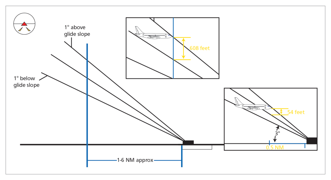
Why it's needed: The ILS glide slope beam diverges from the runway. At different distances, the same 1° of beam error represents very different vertical distances:
| Distance | 1° GS error = vertical distance |
|---|---|
| 6 NM | ~608 ft |
| ½ NM | ~54 ft |
As the aircraft nears the transmitter, the required correction magnitude decreases. Gain scheduling reduces commanded corrections accordingly — from nearly full authority early in the approach to perhaps ½ or ⅓ of original value near the threshold.
Gain Scheduling Methods (in order of sophistication)
| Method | Trigger | Notes |
|---|---|---|
| Time-based | Fixed time after GS capture (e.g. 45 seconds) | Earliest; no actual position data |
| Marker beacon | Passing inner/outer markers | Stepped; now in disuse — markers removed from many airfields |
| Radio Altimeter | Actual RA height | Most accurate; gradual, continuous; no ground signals needed |
11. Dual FDS & Comparator
Large aircraft with 2 FDS (one per pilot) can use the FD Comparator to monitor command bar positions of both systems.
- Pitch difference between the 2 FDS ≥ 1–4°, OR
- Roll difference between the 2 FDS ≥ 3–9°
Comparator Active Conditions
- Both FD switches ON and neither autopilot engaged
- Only active in TOGA or APP mode below 800 ft RA
Comparator Inhibited When:
- On the ground
- Either FD affected by electrical bus transfer
- Failure of either FD sensor or FD itself
- FDS provides integrated attitude/nav steering commands to pilot and/or autopilot via command bars
- FDS has 2 channels: roll (first/primary) and pitch (second/secondary)
- Raw info = unprocessed deviation; Computed info = rate-of-change processed (anticipates corrections)
- FDC failure: computed info lost, raw info may still be available
- TO/GA engagement: 10° NP initial → 15° NP after 60 kt; TO mode exit below 400 ft RA needs both FD switches OFF
- GA pitch command: 15° NP (2-engine), 13° NP initial (single engine)
- Gain scheduling: reduces FD corrections as aircraft approaches ILS transmitter; RA-based = best method
- FD Comparator: removes bars at 1–4° pitch or 3–9° roll difference; only active in TOGA/APP below 800 ft RA
- FMA: green = engaged (top line), white = armed (second line)
Practice Questions & Detailed Answers
- (a) Cruise navigation was a later capability added as FDS technology advanced.
- (c) Take-off mode was added later; the original purpose was landing aid.
- (d) Engine-out procedures are a specific use case, not the original design purpose.
- (a) Source sensors are not the distinction — both can use ILS/VOR inputs.
- (c) Both can be coupled to autopilot or displayed to the pilot.
- (d) Computed information is derived onboard from the FDC; no ground station is involved.
- (a) Reverses the green/amber and line positions — engaged is always top line green.
- (c) White is used for armed modes, not engaged; blue is not a standard FMA colour.
- (d) Armed modes are white, not green; the boxing indicates newly changed modes.
- (a) 10° nose-up is not a standard FD TO command; 10° nose-down is the initial command before 60 kt.
- (b) 15° nose-down would put the aircraft on the ground — obviously incorrect.
- (d) 5° nose-up is not a standard FD TO command value.
- (a) Cost is not the cited advantage; the superiority is operational accuracy.
- (c) The ILS is still required; gain scheduling just optimizes how the FDS responds to GS deviations.
- (d) No specific ICAO requirement for RA-based scheduling is cited; it is a design preference.
- (a), (b) These are larger thresholds than specified — the comparator acts early to alert of divergence.
- (d) ½–1° is too small; minor disagreements within this range are tolerated.
Master Reference Tables
Key Numerical Values — Chapter 25
| Value | Parameter | Section |
|---|---|---|
| 60 kt | IAS at which FD TO pitch changes from 10° ND to 15° NP | 8 |
| 10° NP | FD initial TO pitch command (before 60 kt) | 8 |
| 15° NP | FD TO pitch command after 60 kt; also 2-engine GA pitch command | 8, 9 |
| 13° NP | Initial FD single-engine GA pitch command | 9 |
| 80 kt | Min IAS to engage FD during TO with FD switches off | 8 |
| 400 ft RA | Threshold above which TO mode can be exited by mode selection | 8 |
| 2000 ft RA | Max RA for GA engagement (with FD switches off: 150 sec after liftoff) | 9 |
| 10 sec | Critical time threshold for SE GA target speed determination | 9 |
| 6 NM | 1° GS error ≈ 608 ft vertical | 10 |
| ½ NM | 1° GS error ≈ 54 ft vertical | 10 |
| 1–4° | FD comparator pitch difference trigger | 11 |
| 3–9° | FD comparator roll difference trigger | 11 |
| 800 ft RA | Below this RA, FD comparator becomes active in TOGA/APP | 11 |
Reinforce Chapter 25: Flight Director Systems
Test your knowledge and practice actual exam questions for Navigation — Instrumentation.