Remote Indicating Magnetic Compass
by Ghost Aviator
Table of Contents
- Limitations of the DRMC and DGI
- Requirement for the Gyro-magnetic Compass
- Basic System Description and Components
- Operation with Steady Heading — Gyro Drift Correction
- Operation in a Turn — Gyro Drift Small Over Period of Turn
- Rapid Synchronization
- Detector Unit — The Flux Valve
- Flux Valve — How It Works (Faraday's Law)
- Error Signal Comparison — Rotor-Stator
- Heading Indicator
- Operation as a DGI — FREE Mode vs. SLAVED Mode
- Annunciator
- Keeping the Gyro Axis Horizontal
- Transmitting Heading Output — Selsyn Unit
- Summary
- Practice Questions & Detailed Answers
- Master Reference Tables
1. Limitations of the DRMC and DGI
Direct Reading Magnetic Compass (DRMC) Limitations
- Turning and acceleration errors — cannot be read accurately during a turn.
- Magnetic sensing element is within the instrument, close to the pilot — hence close to deviation sources (lights, motors, ferrous metal in the cockpit).
- Self-contained — cannot feed heading information to other equipment.
Directional Gyro Indicator (DGI) Limitations
- No magnetic element — if the gyro drifts, there is no correction except by the pilot manually synchronizing to the DRMC at regular intervals.
- Turning and acceleration errors are eliminated, and output can be taken to other equipment — but long-term heading accuracy suffers from drift.
2. Requirement for the Gyro-magnetic Compass
The ideal system combines the short-term rigidity of the gyro (overcoming turning and acceleration errors) with the long-term magnetic monitoring of the earth's field (correcting gyro drift via a servo/slaving system). This is the gyro-magnetic compass.
- Gyro-magnetic Compass
- Remote Indicating Compass (RIMC)
- Slaved Gyro Compass
3. Basic System Description and Components
| Component | Alternative Name | Function |
|---|---|---|
| Magnetic Detector Unit | Flux valve / Flux detector | Senses direction of earth's magnetic field |
| Heading Indicator | Compass (HI) | Displays heading to pilot; driven by direct drive shaft from gyro |
| Precession Amplifier | Slaving amplifier | Amplifies, phase-detects, and rectifies the AC error signal to DC |
| Precession Motor | Slaving/synchronizing motor | Driven by DC error signal to turn the gyro |
| Horizontal Gyro | — | Provides short-term stability; directly connected to compass card via direct drive shaft and bevel gear |
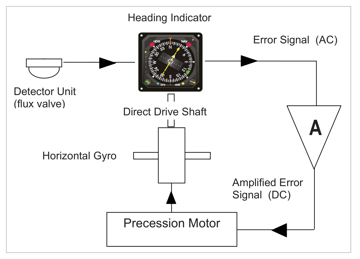
flowchart LR
    FV["Flux Valve\n(Detector Unit)"] --"AC Error Signal"--> AMP["Precession Amplifier\n(Amplify, Phase-detect,\nRectify to DC)"]
    AMP --"DC Signal"--> PM["Precession Motor"]
    PM --"Corrects"--> GY["Horizontal Gyro"]
    GY --"Direct Drive\nShaft (bevel gear)"--> HI["Heading Indicator\n(Compass Card)"]
    HI --"Rotor-Stator\nComparison"--> FV
    HI --"Heading Output\n(Selsyn)"--> OTH["Other Instruments\n(ADI, RMI, FMS...)"]
4. Operation with Steady Heading — Gyro Drift Correction
- The flux valve senses the earth's magnetic field and reproduces it within the compass unit, where it is compared with the position of the gyro drive shaft.
- If the two are aligned → no error signal → compass reads correctly. No action needed.
- If the gyro drifts → drive shaft misaligns with flux valve field → an AC error signal is generated and passed to the precession amplifier.
- The amplifier amplifies, phase-detects, and rectifies the AC error signal to DC.
- The DC signal drives the precession motor, which turns the gyro.
- The gyro output is fed via the direct drive shaft to the heading indicator for comparison with the flux valve signal.
- When aligned → compass synchronized → no further action.
5. Operation in a Turn — Gyro Drift Small Over Period of Turn
During a turn, the aircraft turns but the gyro (having rigidity) does not. The relative rotation between the horizontal gyro and the instrument case operates the bevel gear on the direct drive shaft, changing the heading indication on the compass card. At the same time, the heading sensed by the flux valve is also changing at the same rate. Therefore, no error signal is generated and the compass remains synchronized during the turn.
If there is some gyro drift during the turn, on completion of the turn a small error signal will appear and be corrected at the normal rate of ≈3°/min.
6. Rapid Synchronization
On initial switch-on, the gyro adopts a random alignment unlikely to be synchronized with the earth's magnetic field. At the normal rate of ≈3°/minute, a 90° misalignment would take 30 minutes to correct — unacceptable.
- Mechanical clutch — operated by the pilot (similar to the DGI caging device).
- High gain mode for the precession amplifier — a 2-position switch, spring-loaded to normal, held against the spring for rapid alignment. Increases precession motor correction rate so synchronization takes only a few seconds.
7. Detector Unit — The Flux Valve
The detector unit is positioned in a part of the aircraft least affected by on-board electrical fields — usually the wing tip or tail fin, where aircraft-generated magnetic disturbances are at a minimum.
Its function is to sense the direction of the earth's magnetic field. It contains a pendulous magnetic detecting element mounted on a Hooke's Joint which enables the detector to swing within limits of 25° about the pitch and roll axes, but allows no rotation in azimuth. The unit is contained in a sealed case partially filled with oil to dampen oscillations.
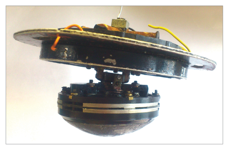
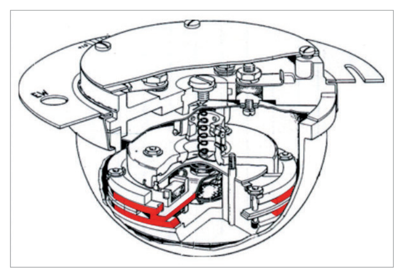
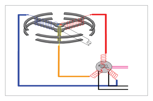
The primary component is the flux valve — a 3-spoked device, fixed in azimuth but with some freedom in the vertical to align with the plane of the earth's magnetic field. The curved 'rams horns' at the end of each leg improve magnetic flux gathering efficiency.
8. Flux Valve — How It Works (Faraday's Law)
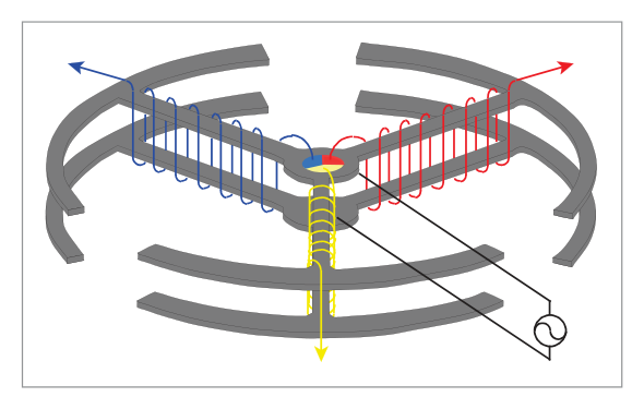
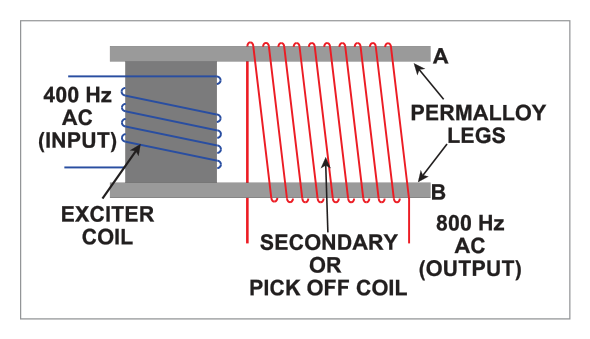
Single Leg Operation
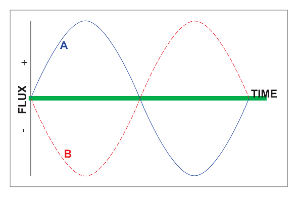
AC is fed to the coil wound around the centre post, producing fields of opposite sign (anti-phase) in the top and bottom legs of the flux valve leg. Without the earth's background field, these two fields cancel → resultant flux = zero → no current in the pick-off coil.
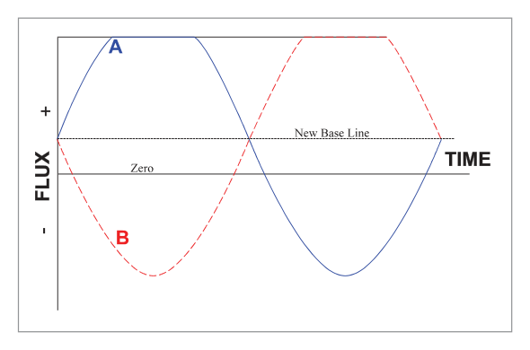
When the earth's magnetic field is present as a background, the positive and negative flux start from a non-zero baseline. The physical characteristics of the flux valve metal are such that it magnetically saturates at a certain level — it will not magnetize further beyond the saturation level.
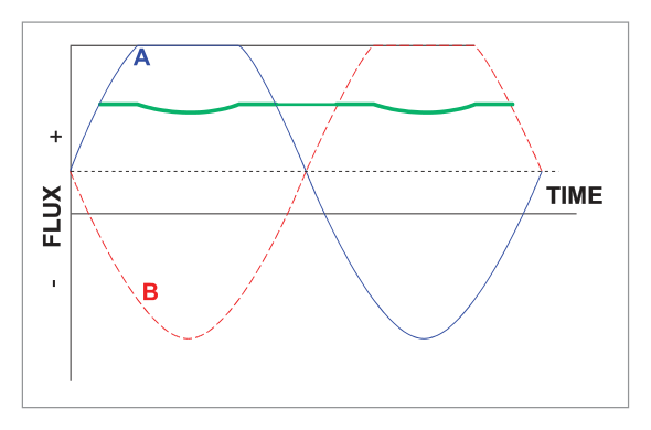
Faraday's Law of Electromagnetic Induction: "If the number of lines of force threading a circuit is changing, an induced electromotive force (EMF) will be set up in the circuit, the magnitude of the EMF being proportional to the rate of change in the number of lines of force threading the circuit."
The secondary winding picks up the change in magnetic flux density (the dips in the resultant flux) as an EMF, detected as an AC signal.
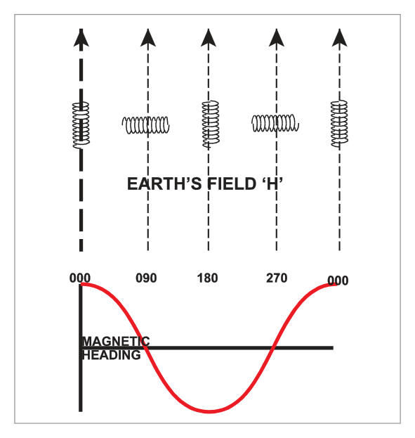
Why 3 Legs Are Needed
The EMF varies as the cosine of the angle between the flux valve leg and the earth's field — but for any given voltage, there are two possible heading values (cos is not a unique function from 0–360°). A single leg cannot unambiguously determine heading.
The 3-leg system solves this: the output from each leg is fed to one of 3 legs of a stator, recreating the earth's field relative to the flux valve direction around the direct drive shaft from the gyro to the heading indicator compass card. The 3-phase output uniquely determines the field direction.
9. Error Signal Comparison — Rotor-Stator
A wound coil (the rotor) is mounted on the gyro drive shaft. If the coil is in line with the AC field generated by the stators, a secondary AC voltage is induced (maximum voltage). If the rotor is at 90° to the AC field (null position), no secondary voltage is induced. At any other position, some voltage is induced.
This secondary voltage = the error signal. It is passed to the precession amplifier where it is:
| Step | Process | Reason |
|---|---|---|
| 1 | Amplified | Un-amplified error signal is not powerful enough to drive the precession motor. |
| 2 | Phase Detected | Determines the sense (direction) of the error — so the motor turns the shortest way (e.g., 2° anticlockwise, not 358° clockwise), preventing continuous rotation. |
| 3 | Rectified to DC | The precession motor is an electromagnetic solenoid acting on a permanent magnet, which requires DC. The DC direction (+ or −) drives the shaft clockwise or anticlockwise. |
10. Heading Indicator
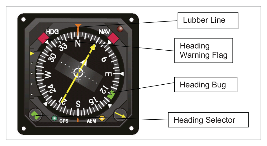
The heading indicator dial (compass card) is directly driven by the shaft from the gyro. The compass card rotates as heading changes and the heading is read against the index line in the 12 o'clock position (the lubber line).
A heading bug (heading select marker) can be set by the pilot to indicate a desired heading. If the magnetic input from the flux valve fails, a heading warning flag appears.
11. Operation as a DGI — FREE Mode vs. SLAVED Mode
| Mode | Description | When Used |
|---|---|---|
| SLAVED | Normal operation: gyro slaved (long-term) to flux valve input. Error correction at ≈3°/min. | Normal operations where flux valve is reliable |
| FREE | Flux valve input disconnected. Rotor/stator comparison ceases. Gyro operates as a free gyro (DGI). No magnetic monitoring. | Flux valve fails, or near magnetic poles where flux valve is unreliable |
12. Annunciator
The annunciator is an indicator positioned in the error signal path between the precession amplifier and the precession motor. During normal flight in SLAVED mode, continuous slight oscillations of heading mean the rotor/stator comparison continuously generates very small error signals. This continuous 'hunting' is normal and by design.
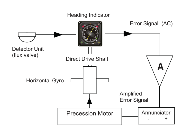
- 1st purpose: Confirms that magnetic monitoring of the gyro is taking place — the compass is 'synchronized' and working normally.
- 2nd purpose: On systems where the pilot must synchronize manually, it indicates which way to turn the compass for synchronization.
13. Keeping the Gyro Axis Horizontal
Gyro wander takes two forms: drift (azimuth wander — handled by the slaving system) and topple (vertical wander — must be corrected separately).
The gyro must be tied either to the aircraft yaw axis or to gravity to stay horizontal. Both methods use a levelling switch and a torque motor:
- Yaw axis method: Inner and outer gimbals maintained at 90° to each other by a system of commutators, insulating strips, and brushes.
- Gravity method: Mercury gravity switches used.
Either way, correcting signals are passed to a torque motor which applies rotational force to the gyro in the yaw axis. The resulting precession returns the gyro to the horizontal — but at a slow precession rate so it does not react wildly to temporary departures (turns, accelerations, climbs, descents).
14. Transmitting Heading Output — Selsyn Unit
Heading information is picked off from the drive shaft between the gyro and the compass card and transmitted to other instruments using a Selsyn Unit (synchro transmitter-receiver pair).
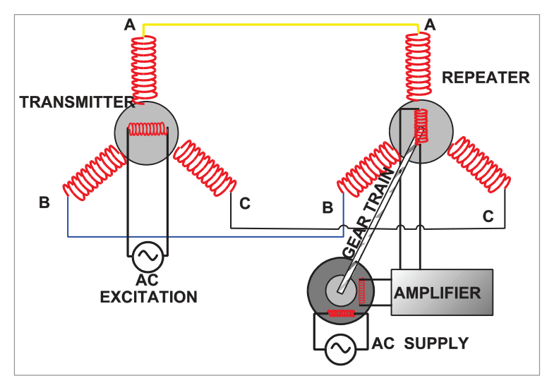
How it works:
- The transmitter rotor is attached to the heading drive shaft and rotates with it. It is supplied with a constant primary AC voltage, which induces a field in the stators.
- The stators are directly connected by 3-strand wire to the 3 stator arms of the repeater, reproducing an identical field there.
- If the repeater rotor is not perpendicular to the repeater stator field, an AC voltage is induced in the repeater rotor, passed to an amplifier and then a motor to turn the repeater shaft until no further voltage is detected.
- The repeater shaft therefore follows any heading changes in the main gyro drive shaft — driving displays in other instruments (RMI, EHSI, autopilot, FMS, etc.).
15. Summary
| Weakness | DRMC | DGI | Gyro-Magnetic Compass |
|---|---|---|---|
| Turning & acceleration errors | Yes (major problem) | Eliminated | Eliminated (gyro stability) |
| Magnetic element close to deviation sources | Yes (in cockpit) | No element at all | Detector in wing/tail — away from sources |
| Can feed other equipment | No | Yes | Yes (Selsyn output) |
| Long-term heading accuracy | Good (north-seeking) | Poor (drift) | Good (slaved to flux valve) |
- Short-term stability of a gyroscope (overcoming turning/acceleration errors).
- Long-term directional stability of the earth's magnetism (correcting gyro drift via the flux valve).
- Gyro-magnetic compass = RIMC = slaved gyro compass. All the same thing.
- 5 components: Flux valve + Heading Indicator + Precession Amplifier + Precession Motor + Horizontal Gyro.
- Normal correction rate: ≈3°/min.
- Rapid sync: a few seconds (high gain mode or mechanical clutch).
- Flux valve: 3-spoked device; position = wing tip or tail fin; freedom ±25° pitch/roll; fixed in azimuth.
- Flux valve principle: Faraday's Law; magnetic saturation of core; earth field creates dips in resultant flux → EMF induced in secondary winding.
- EMF varies as cosine of flux valve leg orientation relative to earth field.
- Error signal: amplified → phase detected → rectified to DC → precession motor.
- Phase detection: ensures motor turns the SHORT WAY to correct the error.
- SLAVED mode: gyro slaved to flux valve. FREE mode: acts as DGI — must be re-set manually.
- Annunciator: indicates synchronization in progress; shows which way to correct in manual sync.
- Gyro topple correction: slow torque motor (yaw axis). Drift correction: slaving to flux valve.
- Heading output to other instruments: Selsyn unit (3-strand wire transmitter-repeater).
- Heading indicator: lubber line at 12 o'clock; heading bug; warning flag on flux valve failure.
Practice Questions & Detailed Answers
1 - a directional gyro 2 - a vertical axis gyro 3 - an earth's magnetic field detector 4 - an azimuth control 5 - a synchronizing control
The combination of correct statements is:
- (a) 2 and 5 — Statement 2 (vertical axis gyro) is wrong; the RIMC uses a horizontal gyro.
- (c) 2, 3 and 5 — Again, statement 2 is wrong.
- (d) 1 and 4 — Incomplete; the flux valve (statement 3) is essential. Statement 4 ("azimuth control") is not a standard component name.
- (a) — The DRMC is a separate backup instrument. The slaved gyro uses the flux valve, not the DRMC, as its magnetic input.
- (b) — The flight director uses heading information from the compass, not the other way round.
- (d) — The air data computer provides airspeed and altitude data, not directional reference.
- (b) — The heading indicator follows the gyro via the drive shaft; the motor does not act directly on the HI.
- (c) — The error detector system (rotor-stator comparison) generates the signal that feeds the motor, not the other way round.
- (d) — The motor is fed by the DC output of the precession amplifier, not directly by the flux valve. The flux valve feeds the amplifier (via the error detection process).
- (b) — "Erector system" usually refers to the AH vertical erection system, not the RIMC.
- (c) — The flux valve signal is not sent directly to the heading indicator. It goes to the error detector first; the heading indicator is driven by the gyro drive shaft.
- (d) — The amplifier receives the error signal from the detector, not directly from the flux valve.
- (a) — The "erection device" refers to the levelling system of the gyro (keeping it horizontal), not the azimuth correction path.
- (c) — The flux valve generates the magnetic field signal, but this goes to the error detector first, not directly to the amplifier.
- (d) — The directional gyro unit's output (drive shaft position) is one input to the error detector, but the amplifier's input is the error signal from the comparator, not the gyro directly.
1 - the flux valve is made of a pair of soft iron bars
2 - the primary coils are fed AC voltage
3 - the information can be used by a "flux gate" compass or a directional gyro
4 - the flux gate valve casing is dependent on the aircraft three inertial axis
5 - the accuracy of the value of the magnetic field indication is less than 0.5%
The combination of correct statements is:
- Statement 2 — CORRECT: The primary coils of the flux valve are fed AC voltage, which creates anti-phase fields in the flux valve legs. See Section 8.
- Statement 3 — CORRECT: The flux valve (flux gate) output can be used by a gyro-magnetic (flux gate) compass or as an input to a DGI slaving system.
- Statement 5 — CORRECT: The flux valve provides high accuracy magnetic field indication (less than 0.5% error).
- Statement 1 — INCORRECT: The flux valve is a 3-spoked device, not a pair of soft iron bars. The legs are made of a material that saturates magnetically at a defined level.
- Statement 4 — INCORRECT: The flux valve casing is fixed in azimuth; it is mounted on a Hooke's Joint giving freedom only in pitch and roll (±25°), not all three inertial axes.
- (b) — Includes statements 1 and 4, both of which are incorrect.
- (c) — Omits statement 2, which is correct (AC feeds primary coils).
- (d) — Includes statements 1 and 4 (both wrong); omits 2 and 3 (both correct).
Master Reference Tables
| Parameter | Value / Description | Section |
|---|---|---|
| Normal precession motor rate | ≈3°/minute | 4 |
| Rapid synchronization time | A few seconds | 6 |
| Without rapid sync — 90° misalignment time | 30 minutes | 6 |
| Flux valve location | Wing tip or tail fin | 7 |
| Flux valve azimuth freedom | Fixed (no azimuth rotation) | 7 |
| Flux valve pitch/roll freedom | ±25° | 7 |
| Flux valve legs | 3 spokes | 7 |
| Primary coil supply | AC voltage | 8 |
| EMF varies as | Cosine of angle to earth's field | 8 |
| Error signal type (before amp) | AC | 9 |
| Error signal type (after amp) | DC (rectified) | 9 |
| Heading indicator read point | Lubber line (12 o'clock) | 10 |
| Selsyn transmitter connection | 3-strand wire to repeater stators | 14 |
Signal Flow Summary
| Step | From | To | Signal Type |
|---|---|---|---|
| 1 | Flux valve | Stators (error detector) | AC (3-phase recreated field) |
| 2 | Stators + Rotor (on drive shaft) | Error signal generated | AC (secondary induced in rotor) |
| 3 | Error signal | Precession amplifier | AC in |
| 4 | Precession amplifier | Precession motor | DC out (phase-detected, rectified) |
| 5 | Precession motor | Horizontal gyro | Mechanical rotation |
| 6 | Horizontal gyro | Compass card (via drive shaft) | Mechanical rotation → heading display |
| 7 | Drive shaft | Selsyn transmitter → other instruments | AC (synchro transmission) |
Answer Key Summary
| Q | Answer | Key Topic |
|---|---|---|
| 1 | b | RIMC = directional gyro (1) + flux valve detector (3) + sync control (5) |
| 2 | c | Slaved gyro takes directional signal from flux valve |
| 3 | a | Torque motor precesses the directional gyro |
| 4 | a | Flux valve signal goes to error detector |
| 5 | b | Amplifier input = error signal from error detector |
| 6 | a | Correct statements: 2 (AC primary), 3 (feeds gyro-magnetic compass), 5 (accuracy <0.5%) |
Reinforce Chapter 17: Remote Indicating Magnetic Compass
Test your knowledge and practice actual exam questions for Navigation — Instrumentation.