Characteristics and General Definitions
by Ghost Aviator
1. Units & Standard Conversions
Pilots must move fluently between metric, imperial and aviation-specific units. The values below are quoted exactly from the source and must be memorised — examiners test the precise figures.
| Quantity | Units | Key conversions (verbatim) |
|---|---|---|
| Distance | Metres, kilometres, feet, nautical & statute miles | 1 NM = 6080 ft or 1852 m; 1 statute mile = 5280 ft or 1609 m |
| Speed | Knots, mph, km/h | 1 knot = 1 NM per hour |
| Mass | Kilogram, pound | — |
| Pressure | hPa/mb, inHg, mmHg, psi | 1 Atmos = 1013.25 hPa = 1013.25 mb = 29.92 inHg = 760 mmHg = 14.7 psi |
| Temperature | Celsius, Kelvin (Absolute), Fahrenheit | MSL = +15°C = +288 K = +59°F |
| Volume | Litres, pints, gallons (Imp & US) | 1 Imp gallon = 1.2 US gallon |
| Angles / Position | Degrees, minutes, seconds | Latitude & longitude shown in Deg Min Sec |
2. Introduction — Common Instrument Problems
Pilots receive information about the aircraft's state — speed, altitude, position and attitude — through instruments and displays. Regardless of vintage, every instrumentation system must contend with four general characteristics:
- Range — the span of values it can display.
- Resolution — the smallest change it can show.
- Accuracy — how closely the indication matches truth.
- Reliability — consistency of correct indication over time.
3. Measuring Range versus Accuracy
It is often necessary to show a large operating range yet still indicate accurately across the whole range. For example, an airliner limited to a maximum permitted airspeed of 350 knots might use an instrument designed to display up to 380 or 400 knots. But safety-critical speeds must be read to the nearest knot. If the entire range is squeezed onto a single revolution, each one-knot division becomes too small to read accurately — that is the range-versus-accuracy conflict.
Circular scale — linear
A simple indicator showing values over a range of 0 to 30 units uses evenly spaced graduations; the required accuracy governs the spacing.
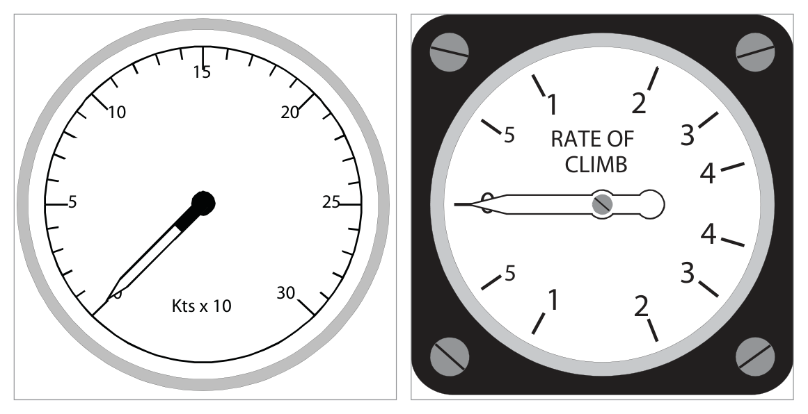
Circular scale — non-linear
Some instruments must show changes more accurately at certain parts of the scale. A rate-of-climb indicator uses a logarithmic scale so that low rates of climb/descent are spread out and easily read, while high rates are compressed.
4. High Range / Long Scale Displays
| Solution | How it works | Example reading |
|---|---|---|
| Single pointer, multiple revolutions | Pointer makes >1 revolution to cover range — can cause confusion | ASI showing 300 kt (Fig 1.3) |
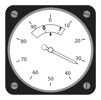
| Moving pointer + moving scale | Pointer over fixed scale (tens), inset moving scale shows hundreds | ASI showing 33 kt (Fig 1.4) |
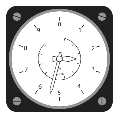
| Two concentric pointers | Small needle/inner scale reads tens; large needle/outer scale reads units | Rev counter showing 25½ % rpm (Fig 1.5) |
| Clock-style (three pointer) | Like hours/minutes/seconds — used on many altimeters | Altimeter showing 25 950 ft (Fig 1.6) |
5. Ergonomy & Standard Panel Layouts
Ergonomy (human engineering) is the science of the relationship between people and machines. For instruments it means designing displays unlikely to be misread and arranging them so interpretation is easy and correct.
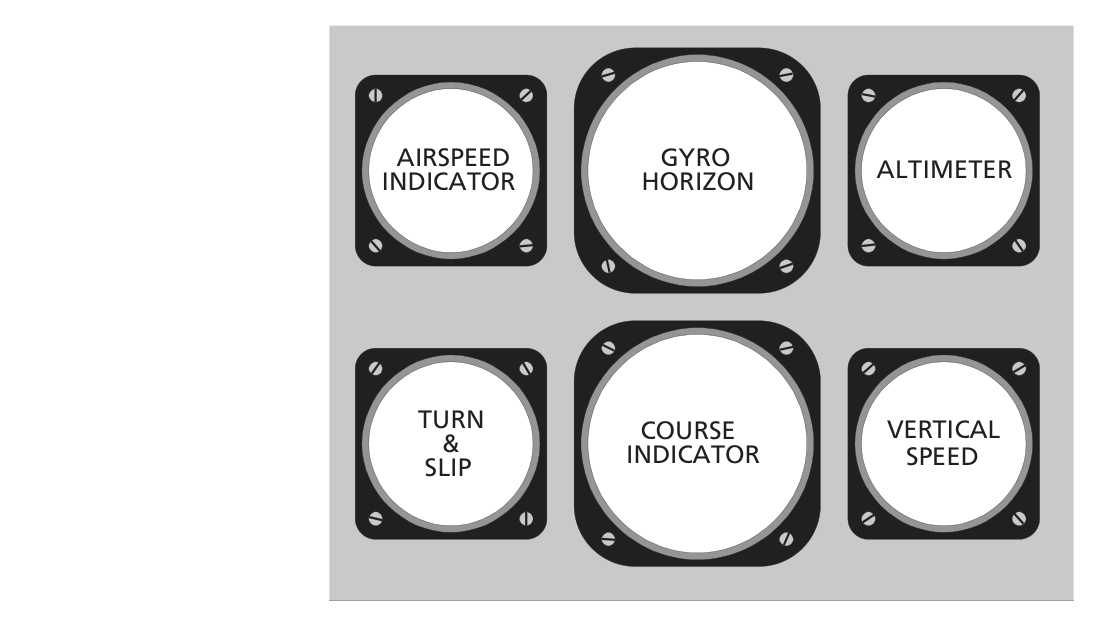
From the "basic six" to the "basic T"
The flying instruments were first arranged as the basic six; other instruments were scattered to suit the manufacturer. Developments then led to the standard basic T.
6. Analogue versus Digital Presentation
Presentation can be analogue (a pointer on a dial) or digital (a row of numbers). With a 3-pointer analogue altimeter, an altitude such as 24 020 ft is harder to absorb at a glance than a digital readout. Digital numbers are easier to read accurately.
7. Electronic (Glass) Displays
Traditionally instruments lived on the instrument panel. With modern electronic displays, the displays remain on the flight deck where the crew can see and operate them, but the computing and power units are located remotely — usually in a separate compartment called the Avionics Bay or the Electrics and Electronics (E&E) Bay.
flowchart LR
  S[Sensors / Probes] --> C[Computing units
in Avionics / E&E Bay]
  P[Power units] --> C
  C --> D[Flight-deck displays
CRT / LCD glass screens]
  D --> Crew([Flight Crew])
8. Readability & Parallax
A readable instrument is designed around an eye reference point — the anticipated position of the pilot's eye in normal viewing. Where an index/reference mark sits in front of a scale, the eye, index and scale must all be in line.
9. Coloured Arcs & Colour Standardization
Conventional (non-electronic) instruments
| Colour | Meaning |
|---|---|
| Green | Normal operating range |
| Yellow / Amber | Cautionary range |
| Red | Warning, or unsafe operating range |
Electronic displays — CS-25 standardization
| Colour | Meaning |
|---|---|
| White | Present status |
| Blue | Temporary situation |
| Green | Normal operating range |
| Yellow / Amber | Cautionary range |
| Red | Warning, or unsafe operating range |
Practice Questions & Detailed Answers
- (a) — 1000 hPa / 28.00 inHg are not the standard values.
- (c) — high-pressure values, not standard.
- (d) — units transposed (inHg and hPa swapped).
- (a) & (b) — 5280 ft / 1609 m define the statute mile.
- (d) — 1000 m is one kilometre.
- (a) — cost is not the stated reason.
- (c) — no such prohibition.
- (d) — the pointer aids rate sensing, not accuracy of the value.
- (a) — position error is a pitot/static pressure error (Ch.2).
- (c) & (d) — hysteresis and lag are mechanical/dynamic errors, not viewing-angle errors.
- (a) — green.
- (c) — red.
- (d) — "present status" is white, and only in the CS-25 electronic set.
Master Reference Tables
All numerical values in this chapter
| Value | Meaning | Section |
|---|---|---|
| 1 NM = 6080 ft = 1852 m | Nautical mile | 1 |
| 1 statute mile = 5280 ft = 1609 m | Statute mile | 1 |
| 1 Imp gal = 1.2 US gal | Volume conversion | 1 |
| 1013.25 hPa / mb | Std MSL pressure | 1 |
| 29.92 inHg / 760 mmHg / 14.7 psi | Std MSL pressure (other units) | 1 |
| +15°C / +288 K / +59°F | Std MSL temperature | 1 |
| 350 / 380–400 kt | Example Vmax vs scale design | 3 |
| 100 / 1000 / 10 000 ft per division | Three-pointer altimeter | 4 |
Memory aids
Answer key
| Q1 | Q2 | Q3 | Q4 | Q5 |
|---|---|---|---|---|
| b | c | b | b | b |
Reinforce Chapter 1: Characteristics and General Definitions
Test your knowledge and practice actual exam questions for Navigation — Instrumentation.