Part II (iv) Radio-navigation aids · Part I (viii) navigation facilities & principal frequencies
Learning objectives — by the end of this chapter you will be able to…
- Explain the four kinds of navigation information radio provides (bearing, distance, vertical guidance, position) and the physical principle behind each.
- Describe the operating principle, frequency band, presentation, range and full error set of NDB/ADF, VOR, ILS and DME — and work numerical bearing/range problems.
- Explain SSR Modes A/C/S, the interrogation/reply pulse scheme, garbling, fruit and side-lobe suppression, and the squawk codes.
- Contrast primary and secondary radar and state the basic pulse-radar relationships.
- Describe GNSS ranging, the need for four satellites, the error budget, DOP, and the augmentation systems (ABAS/SBAS/GBAS) including GAGAN and NavIC.
- Explain PBN (RNAV vs RNP), ACAS/TCAS logic, the radio altimeter, GPWS/EGPWS and INS/IRS.
12.0 How radio creates navigation information
12.1 NDB & ADF
12.2 VOR
12.3 ILS
12.4 DME
12.5 SSR, transponders & Mode S
12.6 Primary radar & radar principles
12.7 GNSS — GPS, GAGAN, NavIC
12.8 PBN — RNAV & RNP
12.9 ACAS / TCAS
12.10 Radio altimeter & GPWS/EGPWS
12.11 INS / IRS

12.0 How radio creates navigation information
Every navigation aid in this chapter answers one of four questions, and each does so by exploiting a single measurable property of a radio wave:
| Question | Physical principle | Aids that use it |
|---|---|---|
| Which direction? (bearing) | Compare the phase or amplitude of signals to extract an angle, or find the null of a directional antenna | ADF (null), VOR (phase), ILS (modulation balance) |
| How far? (distance) | Measure the time a pulse takes to travel out and back; distance = ½ · c · t | DME, primary radar, radio altimeter |
| Where exactly? (position) | Range from several known points (multilateration / satellite ranging) | GNSS, DME/DME, INS (dead reckoning) |
| Am I high/low, left/right of path? | Balance of two overlapping modulated lobes | ILS localizer & glide path, PAR |
Radio waves travel at c = 3 × 10&sup8; m/s. A pulse therefore takes about 12.36 µs to travel one nautical mile and back (the "radar mile"). This single fact underlies DME, radar and the radio altimeter. And bearing systems all reduce to measuring an angle — by phase, by amplitude balance, or by an antenna null.
For any aid, be ready to state four things in order: (1) band, (2) principle, (3) what it gives the pilot, (4) its main errors/limitations. Examiners build almost every nav-aid question from this skeleton.
12.1 NDB & ADF
12.1.1 The ground station (NDB)
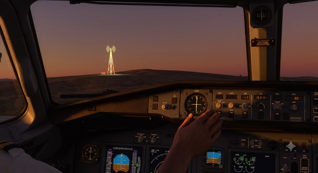
The Non-Directional Beacon is the simplest radio aid: a ground transmitter that radiates equally in all directions (hence "non-directional"). It does nothing clever itself — all the navigation intelligence is in the aircraft's receiver, which determines the direction from which the beacon's signal arrives.
Band: LF/MF, ICAO range 190–1750 kHz (most are 200–415 kHz).
Propagation: primarily ground (surface) wave, which follows the Earth's curvature — giving useful range beyond line-of-sight at low level. Emission: a carrier keyed with a two- or three-letter Morse ident (NON A1A keyed carrier, or NON A2A where a 1020 Hz tone is added so the ident is heard on a standard AM receiver).
Range depends on transmitter power and surface conductivity. As a rule of thumb: Locator (L) beacons (low power, used on approaches) ≈ 10–25 NM; en-route NDBs ≈ 50–100+ NM. Range is greater over sea (high conductivity) than over dry land or mountains.
12.1.2 The airborne receiver (ADF) — how the bearing is found
The Automatic Direction Finder uses a loop antenna whose reception pattern is a figure-of-eight (a "polar diagram" with two lobes and two sharp nulls at right angles to the lobes). A null is used rather than a peak because a null is far sharper and easier to detect precisely. But a single figure-of-eight has two nulls 180° apart — so the loop alone cannot tell whether the station is ahead or behind (180° ambiguity).
To resolve this, the receiver adds an omnidirectional sense antenna (a circular pattern). Combining the loop's figure-of-eight with the sense antenna's circle produces a cardioid (heart-shaped) pattern with a single null. The receiver electronically rotates this pattern (a goniometer/servo) until it finds that single null, and drives the ADF needle to point at the station.
On a fixed-card indicator the needle gives the Relative Bearing (RB) — the angle to the station measured from the aircraft's nose. To get the Magnetic Bearing TO the station (QDM) you add the heading:
(QDR = QDM ± 180°)
On an RMI (Radio Magnetic Indicator) the compass card is slaved to the heading, so the needle reads the magnetic bearing (QDM) directly off the head of the needle.
Aircraft magnetic heading 040°; the ADF relative bearing reads 030° (i.e. 30° to the right of the nose).
QDM (magnetic bearing to the NDB) = RB + HDG = 030 + 040 = 070°.
QDR (magnetic bearing from the NDB) = 070 − 180 = 250°.
If the sum exceeds 360°, subtract 360. E.g. HDG 350°, RB 040° → QDM = 390 − 360 = 030°.
12.1.3 ADF/NDB errors — the full set
| Error | Cause | When worst |
|---|---|---|
| Night effect | After dusk the ionosphere returns a sky wave that contaminates the ground wave; the two interfere and the needle wanders | Dusk & dawn, at longer ranges |
| Coastal (shoreline) refraction | The ground wave changes speed crossing the coast and bends towards the coast | Signal crossing coast at a shallow angle; near the coastline |
| Quadrantal error | The aircraft's own structure re-radiates the signal, biasing the loop | When the station is off the four "quadrantal" headings; reduced by calibration |
| Thunderstorm (static) effect | A CB's electrical discharges radiate strongly in LF/MF; the needle points at the storm | Near active CBs |
| Mountain / terrain effect | Reflections from high ground | Mountainous areas |
| Station interference | At night, distant co-channel beacons are heard via sky wave | Night |
NDB/ADF is the least accurate common aid (system accuracy roughly ±5°). Always confirm the Morse ident before using a beacon, and treat a wandering needle near dusk, coast or a CB with suspicion. Unlike VOR, the NDB gives no failure flag — a needle that has quietly drifted can mislead you.
12.2 VOR — VHF Omnidirectional Range
12.2.1 The phase-comparison principle
A VOR transmits two 30 Hz signals and lets the receiver compare their phase difference to determine the radial. One is a reference phase that is the same in every direction; the other is a variable phase whose timing depends on the bearing of the receiver from the station.
In a conventional VOR (CVOR): the reference 30 Hz is transmitted as frequency modulation on a 9960 Hz sub-carrier (the same everywhere), while the variable 30 Hz is produced as amplitude modulation by physically/electronically rotating a directional pattern at 30 revolutions per second. The two signals are arranged to be exactly in phase when the aircraft is due magnetic NORTH of the station. As you move around the station, the variable phase slips relative to the reference by exactly the bearing angle — so the measured phase difference is the magnetic radial.
Band: VHF 108.0–117.975 MHz (108.00–111.95 shared with ILS — VOR uses the frequencies with an odd first decimal e.g. 108.10; ILS uses even, e.g. 108.10 vs 108.15… check the chart). Propagation: line-of-sight (space wave). Gives: magnetic radial TO or FROM — 360 radials like spokes. Ident: 3-letter Morse, sometimes with voice.
The Doppler VOR (DVOR) reverses the roles (reference = AM, variable = FM produced by Doppler shift from a large ring of antennas electronically "rotated"). The wide antenna ring makes DVOR far less sensitive to site/terrain reflections, so it is more accurate and easier to site. The cockpit indication is identical — the pilot cannot tell CVOR from DVOR.
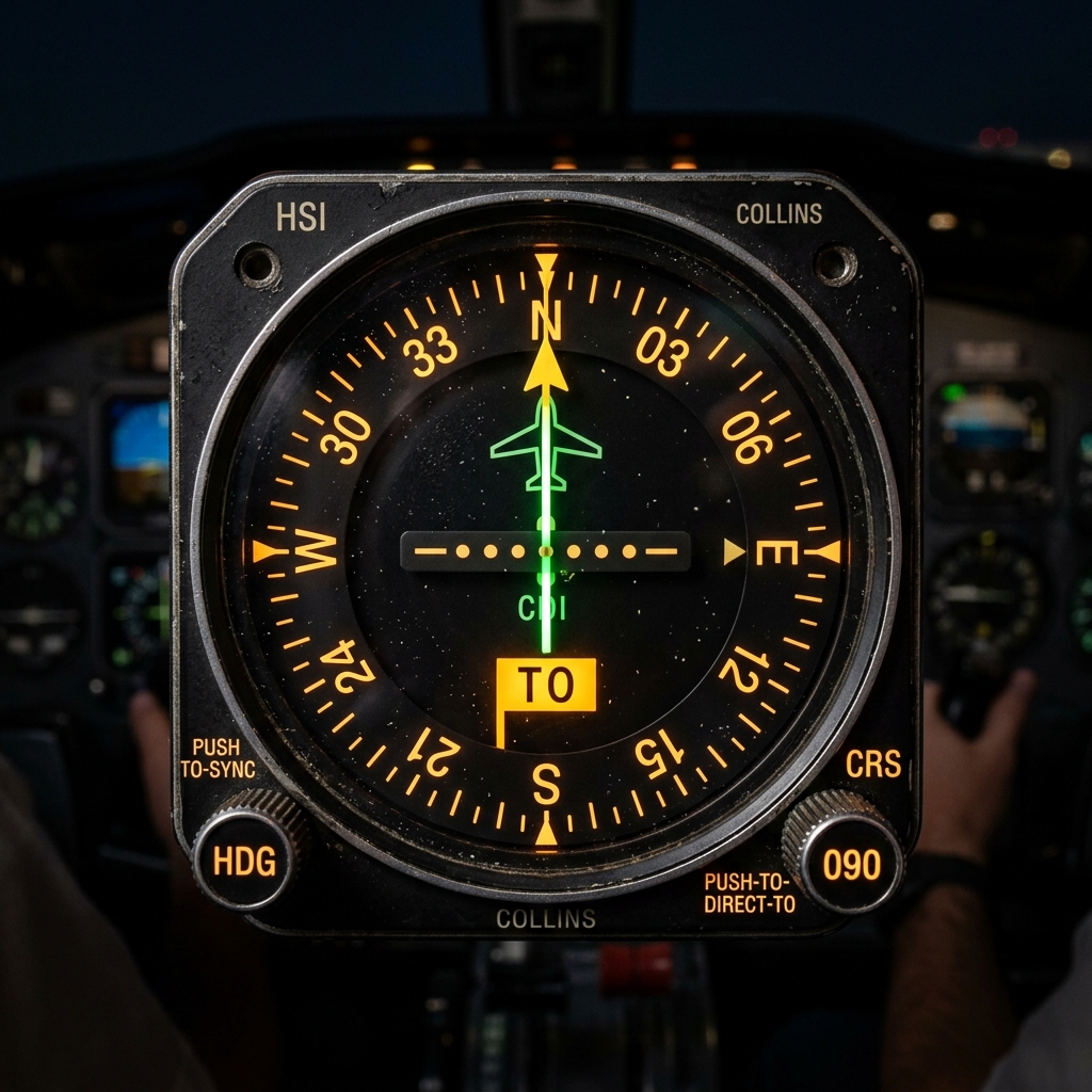
12.2.2 Reading the instrument — OBS, CDI & the TO/FROM flag
You select a course with the OBS (Omni Bearing Selector). The CDI (Course Deviation Indicator) needle shows how far left/right of that selected course you are, and the TO/FROM flag shows whether flying the selected course would take you toward or away from the station. Each dot of CDI deflection ≈ 2°; full-scale (5 dots) ≈ 10°.
You select OBS 090° and get a TO flag with the needle 2 dots left.
TO flag → flying 090° would take you to the station, so the station is roughly east of you (you are west of it, near the 270° radial).
Needle 2 dots left → the selected course is to your left; fly left (turn toward the needle) to intercept. 2 dots ≈ 4° displacement from the 090° course line.
Golden rule: with a FROM flag the CDI senses correctly when your heading roughly matches the OBS; with a TO flag and the OBS set to the reciprocal, beware reverse sensing.
12.2.3 VOR errors & range
| Error / limitation | Detail |
|---|---|
| Site & terrain (scalloping) | Reflections cause the needle to oscillate ("scalloping"); much reduced on DVOR |
| Cone of confusion | Directly overhead the station the signal is ambiguous — the TO/FROM flag flickers and the needle is unreliable for a short time |
| Line-of-sight range | VHF — range grows with altitude; blocked by terrain |
| Aggregate accuracy | ≈ ±5° system (ground station ±1–2°), far better than NDB; a failure flag appears if the signal is unusable |
A VOR is frequently co-located with a DME (VOR/DME) so a single station gives both bearing and distance — a complete fix. TACAN is the military equivalent (bearing + DME in UHF); a VORTAC co-locates a VOR with a TACAN so civil aircraft get VOR bearing + TACAN's DME.
12.3 ILS — Instrument Landing System

The ILS is a precision approach aid giving the pilot both azimuth (left/right of the centreline) and vertical (above/below the glide path) guidance down to low height, plus distance checkpoints. It is built from three independent radio systems.
12.3.1 The localizer — azimuth guidance
An antenna array at the far end of the runway radiates two overlapping lobes along the approach: the left side carries a tone modulated at 90 Hz, the right side at 150 Hz. On the exact centreline the two tones are received with equal depth of modulation — the Difference in Depth of Modulation (DDM) is zero — and the needle centres. Off to one side, one tone dominates and the needle deflects. The receiver literally measures the balance between two modulation tones.
Band: VHF 108.10–111.95 MHz (odd-tenth + 0.05 frequencies). Course sector: adjusted so full-scale deflection corresponds to roughly ±2.5° (course width ≈ runway-width dependent, typically 3–6° total). Sensitivity: about 4× more sensitive than a VOR for the same needle movement — a small deviation moves the needle a lot.
The localizer also radiates a back course off the approach end. Flying inbound on the back course (or a front course outbound) gives reverse sensing — the needle moves opposite to the correction needed — unless the system/HSI compensates. Know this exists.
12.3.2 The glide path — vertical guidance
Band: UHF 329–335 MHz (automatically paired with the localizer frequency — you tune one box). Principle: same 90/150 Hz balance but in the vertical plane — 90 Hz dominates above the path, 150 Hz below. Nominal angle: 3°; usable half-width ≈ ±0.7°.
The glide-path antenna pattern produces additional lobes, creating false glide slopes at higher angles (e.g. around 6°, 9°). They can be captured from above. Defence: intercept the glide path from below at the correct altitude after establishing on the localizer, and cross-check altitude/distance.
12.3.3 Marker beacons & ILS categories
| Marker | Tone / code | Light | Typical position |
|---|---|---|---|
| Outer (OM) | 400 Hz, low tone, dashes | Blue | ≈ 3.9–5 NM (final approach fix) |
| Middle (MM) | 1300 Hz, alternate dot-dash | Amber | ≈ 0.5–0.6 NM (near CAT I DH) |
| Inner (IM) | 3000 Hz, high tone, dots | White | Near threshold (CAT II/III) |
Every marker — outer, middle, inner — transmits on a 75 MHz carrier (VHF), radiating a narrow fan upward; the aircraft passes through it. Markers are increasingly replaced by DME for continuous distance. ICAO categories define the minima:
| Category | Decision Height | RVR (typical) |
|---|---|---|
| CAT I | ≥ 200 ft | ≥ 550 m |
| CAT II | 100–200 ft | ≥ 300 m |
| CAT IIIA | < 100 ft (or none) | ≥ 200 m |
| CAT IIIB | < 50 ft (or none) | 50–200 m |
| CAT IIIC | None | None (zero/zero) |
Confirm exact CAT II/III DH/RVR values against the current DGCA CAR/ICAO Annex 10 & Annex 6, as national thresholds vary slightly. Also confirm protected-area (LSA/GSA critical & sensitive area) wording you wish to include.
12.4 DME — Distance Measuring Equipment
The aircraft (the interrogator) transmits pulse pairs on a UHF frequency. The ground transponder receives them, waits a fixed 50 µs system delay, and replies with pulse pairs on a frequency offset by 63 MHz. The airborne set measures the total round-trip time, subtracts the 50 µs, and converts the remaining time to distance using the radar mile (≈12.36 µs per NM round trip). Because the aircraft initiates and the reply is uniquely jittered, each aircraft recognises only its own replies.
Band: UHF 962–1213 MHz. Gives: slant range (direct line-of-sight distance, not ground distance). Capacity: a ground transponder serves ≈ 100 aircraft; beyond that it sheds the weakest (beacon saturation). Usually paired with a VOR or ILS so one selection drives both.
You are at 6000 ft (≈ 1 NM) overhead-ish a DME, reading 6 NM slant range.
Ground distance = √(slant² − height²) = √(6² − 1²) = √35 ≈ 5.92 NM.
Directly overhead (ground = 0) the DME reads your height in NM: 6000 ft ≈ 1 NM, so it reads ≈ 1 NM, not zero. Slant-range error is greatest close-in and high, and negligible far out at low level.
Holding a constant DME distance while turning lets you fly a DME arc around a station — a common way to join a final approach. The DME's continuous distance is also what replaces marker beacons on a modern ILS ("4 DME", "2 DME" checks against altitude).
12.5 SSR, transponders & Mode S
Unlike primary radar (which listens for a passive echo), Secondary Surveillance Radar is a cooperative system. The ground interrogator transmits on 1030 MHz; the aircraft transponder detects the interrogation and actively replies on 1090 MHz with coded data. Because the reply is a strong, coded transmission rather than a faint echo, SSR gives reliable identity and altitude with far less power.
Mode A (identity): interrogation pulses P1–P3 spaced 8 µs; the reply is a 4096-code (octal) squawk framed between framing pulses F1/F2 (20.3 µs apart). Mode C (altitude): P1–P3 spaced 21 µs; reply encodes pressure altitude in 100 ft steps (Gillham code). Mode S (Select): each aircraft has a unique 24-bit address, so the radar interrogates aircraft individually, carries a data-link, and eliminates the garbling problem. ADS-B (1090ES) is built on the Mode S reply.
| Problem | What it is | Cure |
|---|---|---|
| Garbling | Two aircraft at similar range/bearing reply overlapping in time | Mode S selective addressing |
| FRUIT | Replies triggered by other interrogators received by this radar | Defruiters; Mode S |
| Side-lobe replies | Transponder replies to the radar's antenna side-lobes, giving false bearings | Side-Lobe Suppression (SLS) — a P2 control pulse |
7500 unlawful interference (hijack) · 7600 radio/communications failure · 7700 general emergency. Also: 7000 conspicuity (VFR, many regions), 2000 entering from a non-SSR area, and the SPI / IDENT pulse when ATC asks you to "squawk ident".
"75 taken alive · 76 nix the comms · 77 going to heaven."
12.6 Primary radar & radar principles
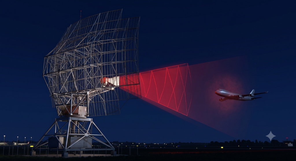
Primary Surveillance Radar (PSR) is the original radar: transmit a pulse, listen for the reflected echo from the target, and time it. It needs no equipment aboard the aircraft, but gives only range and bearing — no identity, no altitude.
Range = ½ · c · t (echo time there-and-back). PRF (pulse repetition frequency) sets the maximum unambiguous range — too high a PRF and a distant echo returns after the next pulse is sent (range ambiguity). Pulse width sets minimum range and range resolution; beam width sets bearing resolution. MTI/Doppler processing rejects stationary clutter to show moving targets.
| Radar | Role |
|---|---|
| ASR / TAR | Airport/terminal surveillance (approach control) |
| ARSR | En-route (area) surveillance — long range |
| SMR | Surface Movement Radar — ground traffic in poor visibility |
| PAR | Precision Approach Radar — controller-guided azimuth + elevation talkdown (Ch 17) |
| Weather radar | Airborne, ~9.3 GHz (X-band), detects precipitation/CB |
12.7 GNSS — GPS, GAGAN & NavIC

12.7.1 How satellite ranging fixes a position
Each satellite broadcasts its position and a precisely-timed code. The receiver measures the time of flight of the code → a range to that satellite, placing the aircraft on a sphere around it. Two satellites narrow it to a circle, three to two points — so in principle 3 satellites give a 3-D position. But the receiver's own clock is cheap and slightly wrong, and a small clock error scales by c into a large range error. A fourth satellite is used to solve for that clock error as well — hence four satellites are required for a 3-D fix.
Space segment: ≥ 24 satellites in 6 orbital planes at ≈ 20,200 km, period ≈ 11 h 58 min, inclination 55°. Signals: L1 = 1575.42 MHz (also L2 1227.6, L5 1176.45 MHz). Control segment: ground monitor/upload stations. User segment: the receiver. Other constellations: GLONASS (Russia), Galileo (EU), BeiDou (China), NavIC/IRNSS (India, regional — L5 & S-band, ~7 satellites).
12.7.2 Error budget, DOP & integrity
| Error source | Note |
|---|---|
| Ionospheric / tropospheric delay | Largest natural error; partly modelled, dual-frequency cancels ionosphere |
| Satellite clock & ephemeris | Corrected by the navigation message |
| Multipath | Reflections off ground/structures near the antenna |
| Receiver noise | Internal |
| Geometry (GDOP/PDOP) | Satellites spread wide across the sky give a strong fix (low DOP); satellites bunched together give a weak fix (high DOP) |
ABAS (Aircraft-Based, e.g. RAIM — Receiver Autonomous Integrity Monitoring): the receiver cross-checks redundant satellites to detect a faulty one. SBAS (Satellite-Based): geostationary satellites broadcast wide-area corrections + integrity — GAGAN (India), WAAS (USA), EGNOS (Europe), enabling APV/LPV approaches. GBAS (Ground-Based, GLS): a local airport station for precision approaches.
GAGAN (GPS Aided GEO Augmented Navigation) uses geostationary satellites to broadcast corrections and an integrity message over the Indian region, improving GPS accuracy to a few metres and enabling approach procedures with vertical guidance. Integrity — the system's ability to warn the pilot promptly when it should not be used — is what makes augmentation essential for IFR approaches.
12.8 PBN — RNAV & RNP
Performance-Based Navigation (PBN) frees aircraft from flying directly station-to-station: instead they fly defined paths to a stated accuracy. The key distinction the exam wants:
RNAV = Area Navigation: fly any path within the coverage of the nav aids, to a stated lateral accuracy. RNP = RNAV plus on-board performance monitoring and alerting — the system continuously checks it is meeting the required accuracy and warns the crew if it is not. That self-monitoring is the whole difference.
| Specification | Lateral accuracy (NM, 95%) | Phase |
|---|---|---|
| RNAV 10 / RNP 10 | 10 | Oceanic / remote |
| RNAV 5 | 5 | En-route continental |
| RNAV 1 / 2 | 1 / 2 | Terminal |
| RNP 4 | 4 | Oceanic (with monitoring) |
| RNP 1 | 1 | Terminal (with monitoring) |
| RNP APCH / AR | 0.3 → lower | Approach (AR = authorisation required, curved paths) |
12.9 ACAS / TCAS
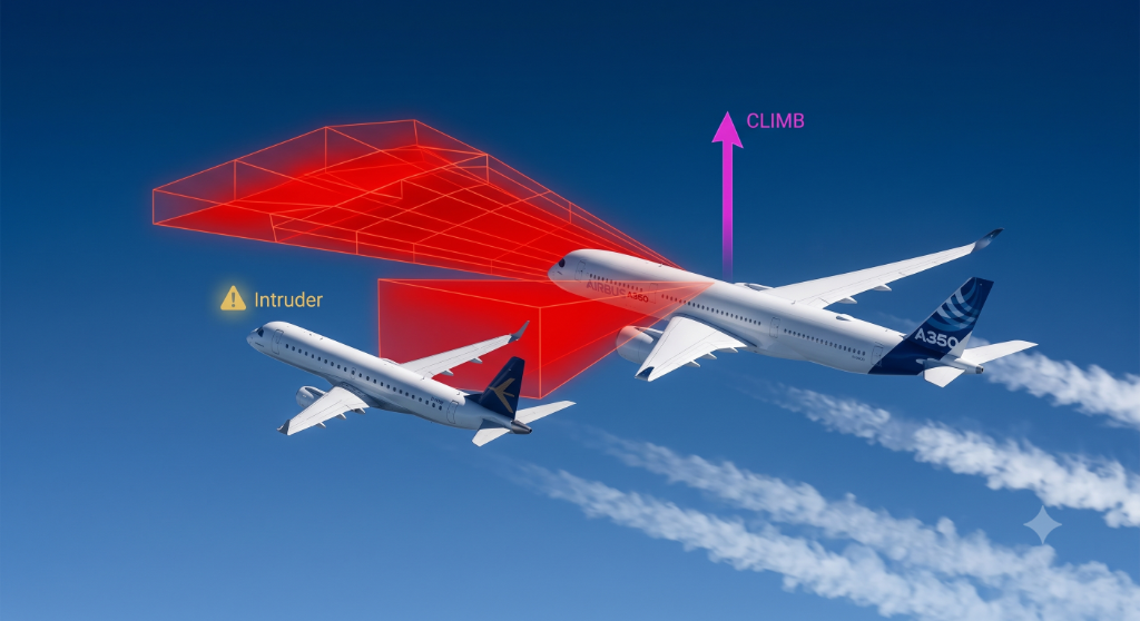
ACAS (the ICAO term; TCAS II is the common implementation) interrogates the transponders of nearby aircraft — exactly like a tiny airborne SSR — and tracks their range, closure and altitude. It builds a picture independent of ground radar and warns of conflicts in the vertical plane.
Traffic Advisory (TA): "TRAFFIC, TRAFFIC" — ≈ 40 s to closest approach; alerts the crew to look out, but commands nothing. Resolution Advisory (RA): ≈ 25 s to closest approach — a vertical command (climb/descend/maintain/level-off). When both aircraft have TCAS II, they coordinate via Mode S so one climbs and the other descends. An RA is followed even if it conflicts with an ATC instruction, and the crew advises ATC ("TCAS RA").
TCAS only sees aircraft with an operating transponder (it cannot see non-transponding traffic). RAs are vertical only — never turn in response to an RA. It is a last-resort safety net, not a substitute for see-and-avoid or ATC separation.
12.10 Radio altimeter & GPWS/EGPWS

Band: ≈ 4200–4400 MHz (SHF). Technique: FM-CW (frequency-modulated continuous wave) — the frequency difference between the transmitted and reflected signal is proportional to height. Measures true height above the surface directly below (AGL), typically 0–2500 ft, used on approach and for auto-land. It reads terrain height, not a barometric level.
The Ground Proximity Warning System uses radio-altimeter height and aircraft data to warn of dangerous situations: 1 excessive descent rate · 2 excessive terrain closure rate · 3 altitude loss after take-off · 4 unsafe terrain clearance (not in landing config) · 5 below glide slope · 6 altitude callouts / excessive bank · 7 wind shear. EGPWS (Enhanced) adds a worldwide terrain database and GPS position for forward-looking terrain alerting — warning of terrain ahead, not just below.
12.11 INS / IRS
An Inertial Navigation System measures the aircraft's own accelerations (accelerometers) and rotations (gyroscopes), and mathematically integrates them from a known start position to compute present position continuously — needing no external radio signal at all. It is therefore completely self-contained and un-jammable.
Older systems use a gimballed stable platform; modern strapdown IRS fix the sensors to the airframe and use ring-laser or fibre-optic gyros. Because errors accumulate through integration, the position drifts with time (typically ≈ 2 NM/hr). Schuler tuning (an 84.4-minute period) prevents the system oscillating with vehicle motion. In practice the IRS is blended with GNSS (hybrid IRS/GPS) so GNSS bounds the drift while inertial provides smooth, high-rate, jam-resistant data.
☆ Numbers to memorise
| Aid | Band / frequency | Principle | Gives / key figures |
|---|---|---|---|
| NDB / ADF | LF/MF 190–1750 kHz | Loop null + sense → cardioid | Relative bearing; ±5°; ground wave |
| VOR | VHF 108.0–117.975 MHz | 30 Hz phase comparison (ref FM / var AM) | Magnetic radial; ±5°; in-phase at North |
| ILS LOC | VHF 108.10–111.95 MHz | 90/150 Hz DDM balance (azimuth) | Centreline; ±2.5° full scale |
| ILS GP | UHF 329–335 MHz | 90 above /150 below (vertical) | 3° path; false slopes ~6°/9° |
| Markers | 75 MHz (OM 400/MM 1300/IM 3000 Hz) | Vertical fan | Distance checkpoints |
| DME | UHF 962–1213 MHz | Pulse-pair timing; 50 µs delay; 63 MHz offset | Slant range; ~100 a/c; radar mile 12.36 µs/NM |
| SSR | 1030 ↑ / 1090 ↓ MHz | Interrogate–reply; Mode A 8 µs / C 21 µs / S 24-bit | ID + altitude; 7500/7600/7700 |
| GPS | L1 1575.42 MHz | Satellite pseudo-ranging | 4 sats for 3-D; ~20,200 km; GAGAN augments |
| Radio altimeter | 4200–4400 MHz | FM-CW | True AGL 0–2500 ft |
| INS/IRS | (no radio) | Accelerometers + gyros | Self-contained; drift ~2 NM/hr; Schuler 84.4 min |
Part A — MCQs (click an option to check)
Part B — Oral / viva (tap to reveal model answers)
Part C — Numerical problems (tap for worked solutions)
60-SECOND REVISION CARD
- ADF/NDB LF/MF, loop-null+sense→cardioid, RB (QDM=RB+HDG), ±5°, many errors, no flag.
- VOR VHF, 30 Hz phase (ref FM/var AM), in-phase at North, radials, ±5°, cone of confusion, flag.
- ILS LOC VHF 90/150 DDM; GP UHF 329–335 (90 above/150 below, 3°, false slopes); markers 75 MHz; CAT I–III.
- DME UHF 962–1213, pulse timing, 50 µs delay, slant range, ~100 a/c.
- SSR 1030↑/1090↓, Mode A/C/S, SLS/garble/FRUIT, 7500/7600/7700.
- GNSS L1 1575.42, 4 sats for 3-D, DOP, augment ABAS/SBAS(GAGAN)/GBAS; NavIC=India constellation.
- RNP=RNAV+monitoring/alerting. TCAS vertical RA, Mode-S coordinated. RadAlt 4200–4400 FM-CW AGL. INS self-contained, drifts ~2 NM/hr.